2.7Partsrequired
Additionalpartsrequired,NOTsuppliedwiththeproduct.
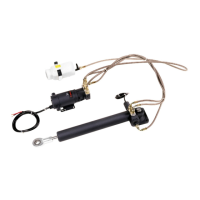
Thefollowingadditionalpartsarerequiredfortheinstallationofthe
HydraulicLinearDrive:
•Suitableboltsandassociatednutsandwashersforsecuringthe
reservoirtoasuitablepartofyourvessel.Quantityrequired:2.
•Suitableboltsandassociatednutsandwashersforsecuringthe
pumptoasuitablepartofyourvessel.Quantityrequired:2.
•Suitablecableandelectricalconnectorsforconnectingand
extendingthemotorandclutchcables.
2.8Locationandmountingrequirements
Hydraulicram
Locationandmountingrequirements:
•MUSTbemountedonaverysolidstructure(forexample,a
substantialframememberofyourvessel).Thedriveproducesa
considerableamountofforce,soyouMUSTensurethatboththe
structureandyourtillerarmorrudderquadrantcancopewiththe
peaklevelsofthruststatedintheT echnicalSpecicationinthis
document.Insomecasesitmaybenecessarytobuildaspecially
strengthenedframetomountthedriveunit.Consultthesteering
gearmanufacturerifyouhaveanydoubtaboutthestrengthofthe
tillerarmorrudderquadrant.
•TheType2drivemaybemountedhorizontallyorvertically.
•TheType3driveMUSTbemountedhorizontallywithitsmounting
footonahorizontalsurface.TheswiveljointdoesNOThave
sufcientmovementtopositionthefootvertically.
•ThehydraulicrammustNOTfoulanypartofthevessel’sstructure
orquadrantthroughoutitsentirerangeofmovement.
•MUSTbemountedinalocationallowingsufcientclearancefor
themountingpintoberemovedifrequired.
•MUSTbemountedwithsufcientclearanceattherearoftheram
unitforthehydraulicpipes.Youmustallowatleast17cm(6.7in)
clearanceattherearoftheunitfortheextrudingpipes.
•MUSTbettedinadryarea,freeofbilgewater(theramisNOT
waterproof).
•MUSTbeaccessibleforfutureservicing.
•ThesuppliedM8boltsandwashersaresuitableformounting
thehydraulicramtoasurfacebetween1.2cm(0.47in)and2.4
cm(0.94in)thick.Largerboltsandwashersarerequiredfor
athickersurface.
Thefollowingdiagramsillustratethecorrectdriveorientation,
showingaviewfromabovewiththearrowindicatingtheaftdirection:
16
HydraulicLinearDriveInstallationinstructions
 Loading...