3.3Selectingalocation
W
arningsandcautions
Important:Beforeproceeding,ensurethatyouhavereadandunderstoodthewarningsand
cautionsprovidedintheChapter1Importantinformationsectionofthisdocument.
W
arning:2personinstallationrequired
T
opreventpotentialproductdamage,vesseldamageandpersonalinjury
2-personinstallationisrecommended.
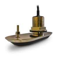
L ocationrequirements
Followtheguidelinesbelowwhenselectingalocationforyoursingletransducerorsplit-pair
transducers.
Forbestperformance,transducersshouldbeinstalledinalocationwiththeleastturbulenceand
aeration.
Important:DoNO Tinstalltransducersin-linewithtrailerrollers,yourvessel’sengineintakeor
dischargeopenings.
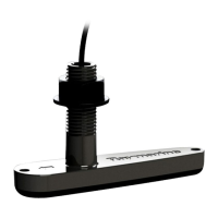
•T ransducersshouldbeinstalledasclosetothecenterlineofthevesselaspossible.
•Themountingsurfaceforthetransducersshouldbeflatsothatthesuppliedrubberwashersits
firmlyagainstthehull.
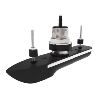
•Wheninstallingsplit-pairtransducerswithangledelements,youmustensurethatthehull’s
deadriseangleatthechosenmountinglocationisappropriatefortheselectedtransducers.
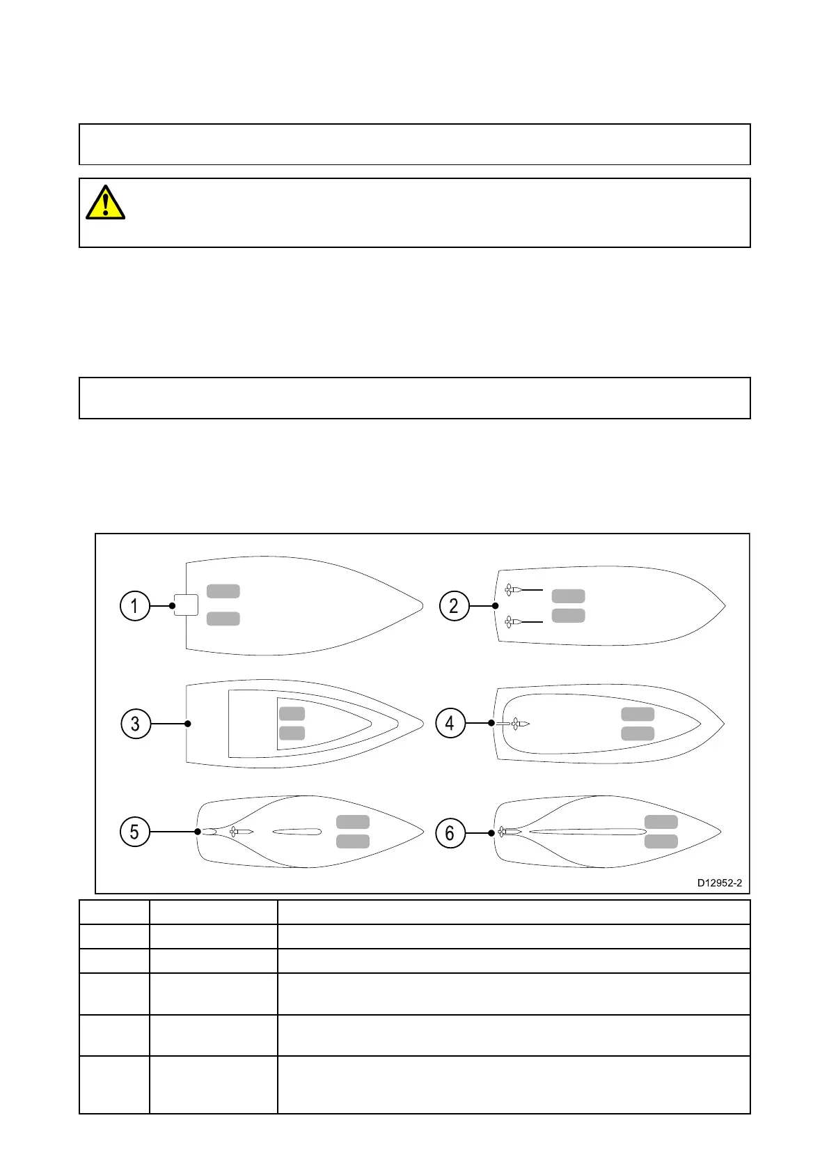
1Planinghull
OutboardorI/O—mountforwardandtothesideofthepropeller(s).
2
Planinghull
Inboard—mountforwardofthepropeller(s)andshaft(s).
3
Planinghull
S teppedhull—mountonthefirststepasfaraftaspossible.
4Displacement
hull
Displacementhull—mountappro ximately1/3ofthewayalongthe
lengthofthehull,measuredalongthewaterline.
5K eelsailboat
Finkeel—mountforwardofthekeel,ensuringthatthekeelwillnot
obstructthetransducerswidebeamwidth.
6
K eelsailboat
Fullkeel—mountawayfromthekeelatalocationwithminimum
deadrise,ensuringthatthekeelwillnotobstructthetransducers
widebeamwidth.
22
 Loading...