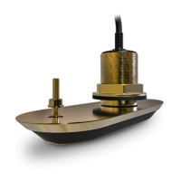
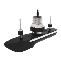
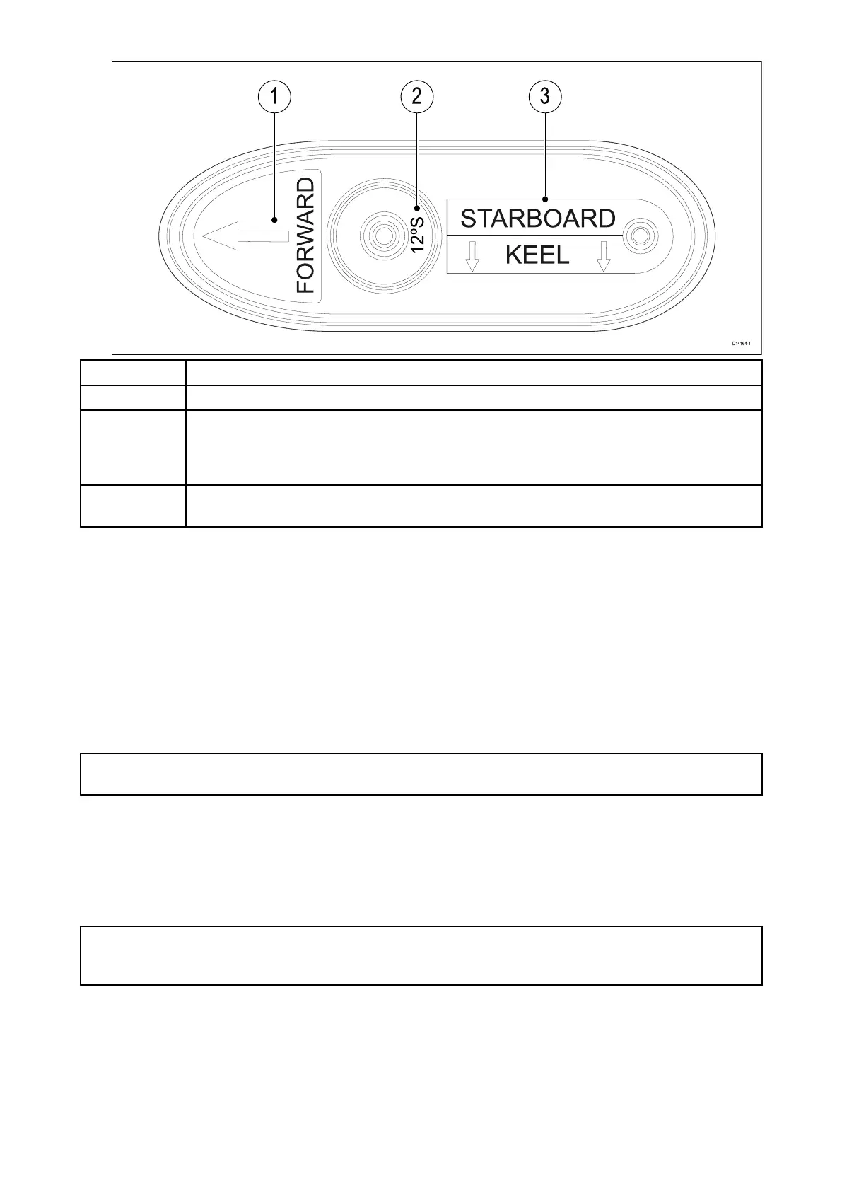
ItemDescription
1Directiontovesselbow
2
Elementangleandvesselside:
–(“12°”;“20°”)
–(port,“P”;starboard,“S”)
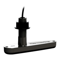
Single(all-in-one)transducersaremark ed“0°”.
3
V esselsideanddirectiontovesselkeel
Single(all-in-one)transducersomitthislabel.
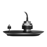
–choosemountingpositionsthataresymmetricaboutthecenterlineofthevessel.
–choosemountingpositionsthatareatleast300mm(12inches)belowthewaterline .
•Transducersshouldbeinstalledinalocationwherethereissufficientclearanceinsidethehullto
fitthenutandhaveatleast100mm(4in)ofheadroomtoallowforwithdrawal.
•Toavoidinterferencewiththeinternalmagnetometer,mounttransducersatleast1m(39inches)
fromotherelectricaldevices.
Coredfiberglasshullmounting
Itisrecommendedthatthetransducerismountedinanon-coredsection,ifinstallationinacored
sectionisrequiredthentheareaaroundtheholemustbeadequatelystrengthenedtoensureitis
notdamagedwhentighteningthehullandanti-rotationnuts.
Important:Installationinacoredfiberglasshullshouldonlybecarriedoutbyacompetent
marineinstaller .
EMCinstallationguidelines
R aymarineequipmentandaccessoriesconformtotheappropriateElectromagneticCompatibility
(EMC)regulations,tominimizeelectromagneticinterferencebetweenequipmentandminimizethe
effectsuchinterferencecouldhaveontheperformanceofyoursystem
CorrectinstallationisrequiredtoensurethatEMCperformanceisnotcompromised.
Note:Inareasofe xtremeEMCinterference,someslightinterferencemaybenoticedonthe
product.Wherethisoccurstheproductandthesourceoftheinterferenceshouldbeseparated
byagreaterdistance.
ForoptimumEMCperformancewerecommendthatwhereverpossible:
•R aymarineequipmentandcablesconnectedtoitare:
–Atleast1m(3.3ft)fromanyequipmenttransmittingorcablescarryingradiosignalse.g.VHF
radios,cablesandantennas.InthecaseofSSBradios,thedistanceshouldbeincreasedto2
m(6.6ft).
–Morethan2m(6.6ft)fromthepathofaradarbeam.Aradarbeamcannormallybeassumedto
spread20degreesaboveandbelowtheradiatingelement.
24
 Loading...