Do you have a question about the Raymarine SL70M and is the answer not in the manual?
Warning about high voltage within the unit and user service limitations.
Information on electromagnetic energy emitted by the scanner and safety measures.
Clarification that the unit is an aid to navigation and user responsibility.
Details regarding the product warranty terms and conditions.
Information on the equipment's compliance with Electromagnetic Compatibility standards.
Explanation of characteristics specific to TFT Color LCD displays.
Guide on how to navigate the manual's structure and content.
General overview of the Pathfinder PLUS Radar system components and features.
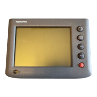
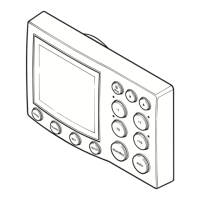
Detailed description of the Pathfinder Radar PLUS display features and options.
Explanation of the various controls used to operate the radar display.
Introduction to standard radar operations and key topics covered in the chapter.
How to control the radar's viewing range and understand range scales.
Guidance on understanding radar echoes and adjusting picture settings.
Using Variable Range Markers and Electronic Bearing Lines for measurements.
How to set up guard zones and manage associated alarms.
Introduction to the Mini Automatic Radar Plotting Aid function for target tracking.
Introduction to setting up system parameters and customizing preferences.
Instructions on how to display and change system setup parameters.
Details on system parameters, their options, and factory defaults.
Specific parameters for setting up the radar display and functions.
Parameters for configuring MARPA target tracking features.
Advanced settings for fine-tuning radar performance.
Introduction to the installation process and system connection guidelines.
Steps for unpacking and verifying all system components are present.
Considerations for choosing the optimal mounting location for the display unit.
Guidelines for routing system cables safely and effectively.
Instructions for mounting the display unit using brackets or flush mounting.
Details on connecting the display unit to power and other system components.
Procedures for testing the installed radar system and performing alignment.
Information on linking the display to other equipment for data transfer.
Verifying data transfer and operation in integrated system configurations.
General specifications and approvals for the 7" SL70 PLUS Series Displays.
Lists key features and capabilities of the radar system.
Details the interfacing capabilities with SeaTalk and NMEA protocols.
Defines data received on NMEA/SeaTalk ports and their priority sources.
Lists data transmitted by the display unit on SeaTalk and NMEA Out.
Connection details for a Raymarine G-Series course computer as a heading source.
Introduction to getting started with the display unit and its functions.
Explains the typographical conventions used throughout the handbook.
Information on using the display's simulator function for practice.
Instructions on how to power the display on/off and switch modes.
Instructions on how to properly turn off the radar display unit.
How to activate and use the simulator mode for practice.
Adjusting backlight and contrast settings on the SL70M mono display.
Adjusting screen brightness on the SL70C color display.
How to select display modes and manage screen presentation.
How to select and display data in half-screen windows.
Options for customizing screen elements like cursor, range rings, and data boxes.
How to display the active waypoint on the radar picture.
Functions for controlling the radar display, including zoom and offset.
How to use the zoom function to magnify areas on the SL70M display.
How to use the zoom function to magnify areas on the SL70C display.
How to move the radar picture's center point off the vessel's position.
Temporarily hiding the Ship's Heading Marker for better target visibility.
How to control the radar's viewing range and understand range scales.
Step-by-step instructions on how to change the radar's range scale.
Explains how to determine the maximum radar range based on line-of-sight.
Guidance on understanding radar echoes and adjusting picture settings.
Guidance on identifying and minimizing false radar echoes like side lobes.
How to adjust gain and sea clutter controls for optimal picture clarity.
Details on adjusting gain settings for different ranges and target visibility.
How to use the sea clutter control to reduce unwanted echoes from waves.
How to fine-tune the receiver for maximum target returns on all range scales.
How to use RAIN and FTC controls to reduce clutter from rain or snow.
How to improve target visibility using interference rejection, expansion, and wakes.
Using Variable Range Markers and Electronic Bearing Lines for measurements.
How to measure range and bearing to a target from the vessel's position.
Step-by-step guide to placing and positioning VRM/EBLs on the display.
How to remove a VRM/EBL from the radar display.
How to measure range and bearing between two points using the Float function.
Procedures for floating a VRM/EBL pair to measure between targets.
How to switch VRM/EBL data boxes on/off and move them.
How to set up guard zones and manage associated alarms.
Step-by-step guide to placing sector or circular guard zones on the radar.
How to move, reshape, or delete existing guard zones using the cursor.
How to set alarm sensitivity and manage guard zone alarms.
Introduction to the Mini Automatic Radar Plotting Aid function for target tracking.
Overview of MARPA's purpose for collision avoidance and target tracking.
How targets are assessed for danger and potential collision warnings.
Information displayed for MARPA tracked targets and their status symbols.
How to display and interpret target vectors and historical movement data.
How MARPA data is sent via NMEA to other equipment.
Available radar range scales for MARPA target acquisition.
How to access and use MARPA functions like acquiring and cancelling targets.
How to view or hide MARPA target data boxes using cursor or soft keys.
Introduction to displaying non-radar information and using MOB function.
How to change the radar picture's orientation between Head Up, North Up, and Course Up.
Explains the difference between relative and true motion display modes.
Details the three heading modes: Head Up, North Up, and Course Up.
How to change the heading and motion mode using the HDG MODE key.
How heading mode selection affects the behavior of VRM/EBLs.
How to place, move, and delete radar marks on the display.
Step-by-step instructions for placing a mark at the cursor or vessel position.
How to move or delete marks using the context-sensitive cursor.
Instructions on how to use the Man Overboard (MOB) function to return to a lost person/object.
How to display cursors from other connected displays on the radar or chart.
Routine maintenance procedures and cleaning instructions for the display unit.
Periodic checks for display cleanliness and cable integrity.
Specific instructions for cleaning the SL70C display screen safely.
Safety guidelines for servicing and maintaining the equipment, focusing on EMC.
Information on different types of system resets available for the display.
Troubleshooting common problems and solutions for the Raymarine unit.
Information on how to get technical support via website or phone.
Contact information and procedures for Raymarine product and service support in the US.
Contact information for Raymarine support, service, and accessories in Europe.
Information on contacting authorized distributors for worldwide support.
| Resolution | 320 x 240 pixels |
|---|---|
| Waterproof Rating | IPX6 |
| Type | Radar |
| Display Size | 7 inches |
| Frequency | 9.4 GHz |
| Range | Up to 24 nautical miles |