Chapter 1: System connections 7
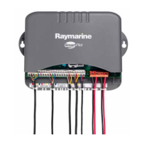
T o con nect the power and drive unit co nnections to the SmartP ilot computer,
follow the step s below:
Power supply to SmartPilot computer
(CABLE NO T SUPPLIED)
1. Measure the total length of cable run from the boat’ s distribution panel to the
SmartPi lot computer .
2. Obtain the appro priate cable as specified.
3. Ensure you use an appropriate circuit breaker or fuse:
4. Route the cable from the distribution panel back to the SmartPilot computer .
5. Connect the cabl es to the
POWER
inpu ts .
Cabl e length Cable g auge Coppe r area
up to 6m (23ft) 14 AWG 2.5 mm
2
Fuse = 15 A
Circuit break er = 10 A
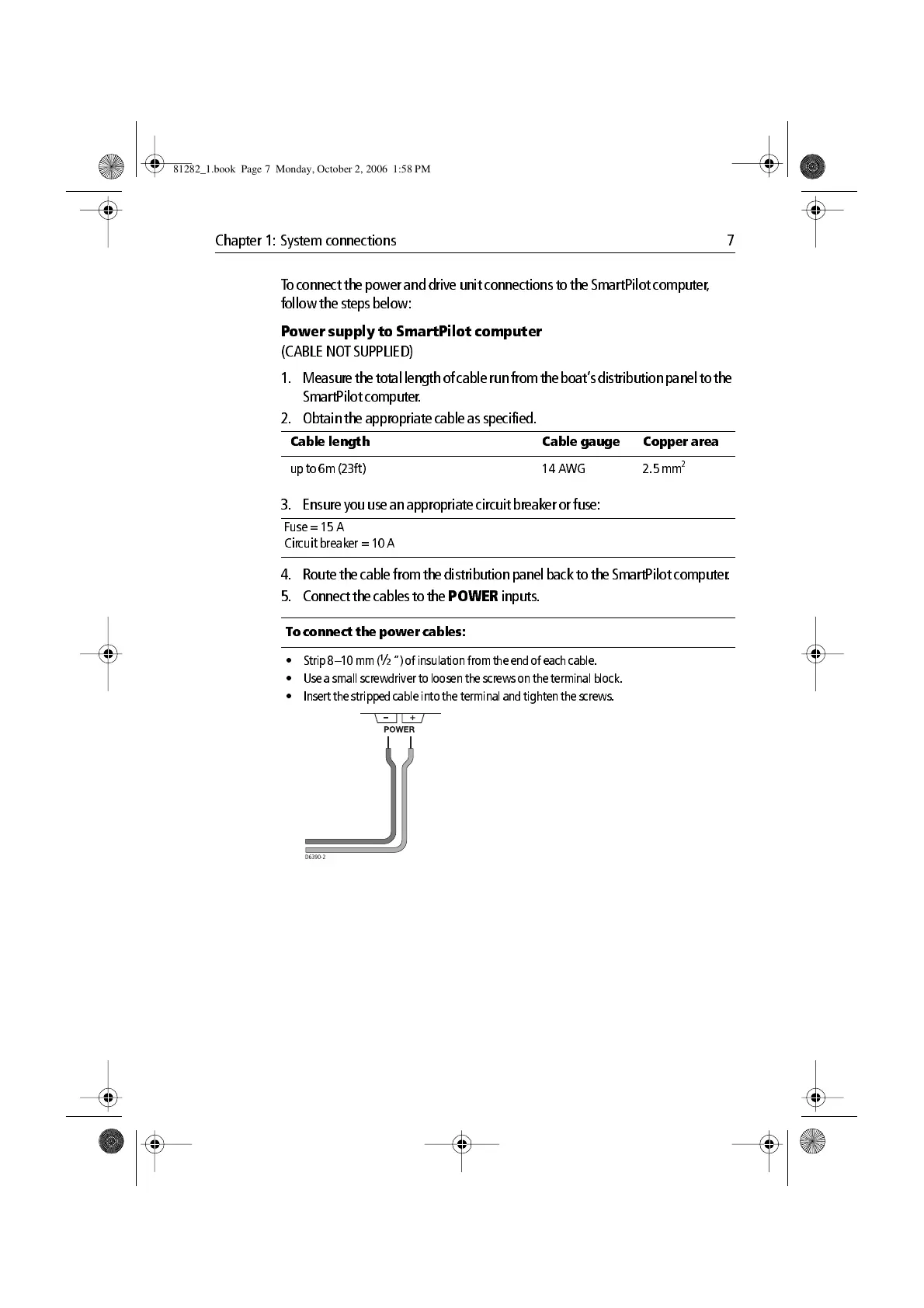
To connect the power c ables:
• Strip 8–10 mm (
½
“) o f insul ation from the end of eac h cable .
• Use a small scre wdrive r to loos en the sc rews on the terminal b lock.
• Insert the strippe d cable into the te rminal and tighte n the scre ws.
D6390-2
81282_1.book Page 7 Monday, October 2, 2006 1:58 PM

 Loading...