Chapter 1: System connections 9
1.5 Fuse Protection
The
POWER
and
SeaT alk
terminal s are fu se protected again st short circu its
and mi sconnections .
Y our Sm artPilot comput er is supplied with spare fuses. The fuses used in the
comp uter are standard automotive blade fuses, so replacements are easily
avail able. Y our Raymarine dealer can also provide a replacement fuse pack.
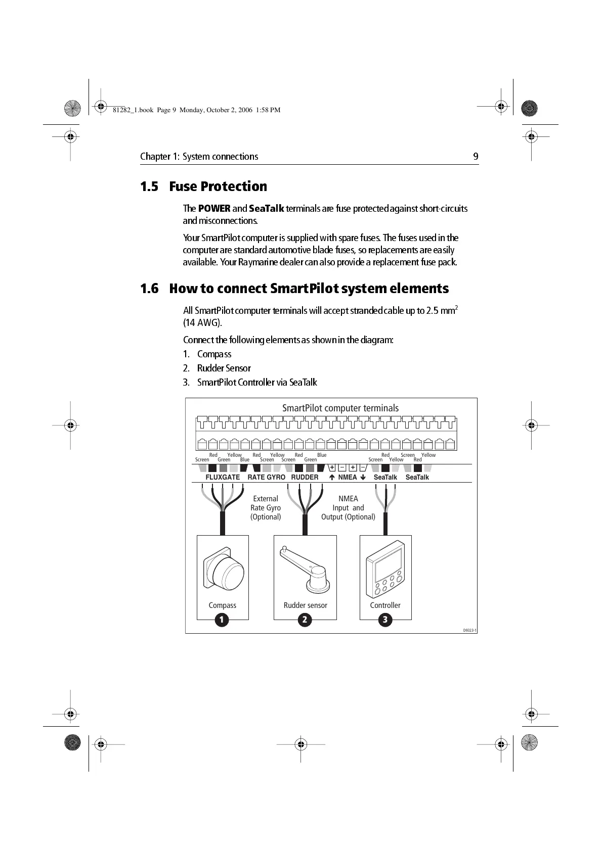
1.6 How to connect SmartPilot system elements
All Sma rtPilot computer terminals will accept stranded cable u p to 2.5 mm
2
(14 AWG).
Conn ect the following elements as shown in the di agram:
1. Compass
2. Rudder Sensor
3. SmartPilot Con troller via SeaT alk
SmartPilot computer terminals
D9323-1
Screen Blue
Red Yellow
Green Screen
BlueRed
Green
Red Yellow
Screen
Red
YellowScreen
Red
YellowScreen
SeaTalkSeaTalk
NMEARUDDERRATE GYROFLUXGATE
1 2 3
Compass
Rudder sensor
External
Rate Gyro
(Optional)
Controller
NMEA
Input and
Output (Optional)
81282_1.book Page 9 Monday, October 2, 2006 1:58 PM

 Loading...