Do you have a question about the Raymarine SPX-5 and is the answer not in the manual?
Provides warnings and precautions for product installation, operation, and navigational safety.
Details compliance with Electromagnetic Compatibility (EMC) regulations for marine environments.
Specifies restrictions on pressure washing Raymarine products to avoid damage and warranty invalidation.
Lists associated documents for the SmartPilot X-5 series and where to download them.
Information on how to register your Raymarine product to receive full warranty benefits.
Guidelines for the proper disposal of electrical and electronic equipment (WEEE Directive).
Outlines the two stages of installation: planning and mounting components for the SPX-5 Wheel system.
Emphasizes the importance of professional installation and certified installation for warranty benefits.
Provides contact information for assistance with system installation.
Describes the SPX-5 Wheel system components and their connection via SeaTalk bus.
Explains how the autopilot integrates with other marine industry standard protocols.
Illustrates a typical system configuration showing SeaTalk connections between instruments.
Lists all necessary components and tools required for system installation.
Details all the components included in the SPX-5 Wheel system kit.
Lists the tools, cables, and optional equipment that must be supplied by the user.
Recommends creating a schematic diagram to plan a safe and optimum system installation.
Covers essential safety warnings and EMC installation guidelines for a safe setup.
Provides basic rules for cabling, including mixing AC/DC, EMC adherence, and cable protection.
Details the correct cable dimensions (copper area and AWG) based on total cable length.
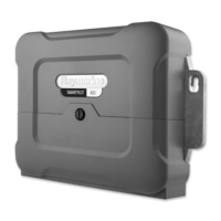
Information on the Course Computer, including its mounting requirements.
Instructions on mounting the Course Computer on a secure, vibration-free vertical surface.
Diagram showing the system connections available on the Course Computer.
Details on how to fit the Wheel Drive unit onto the boat's steering wheel.
Procedure for removing the front cover and drilling spoke clamp holes on the wheel drive.
Instructions for using the template and fitting spoke clamps to secure the drive unit to the wheel.
Steps for attaching the pedestal bracket, including options for motor tube location.
Guidance on measuring, cutting, and positioning the pedestal bracket for correct installation.
Procedure for connecting the waterproof cable to the Wheel Drive socket.
Instructions for routing the Wheel Drive cable to the Course Computer, ensuring it does not foul steering.
Details on connecting power cables from the distribution panel to the Course Computer.
Instructions for installing and connecting the Fluxgate Compass.
Guidance on locating the compass for best performance and connecting its cable.
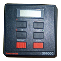
Information on fitting and connecting the ST6002 Pilot Controller to the SeaTalk bus.
Diagram illustrating the connection of the Pilot Controller to the Course Computer's SeaTalk terminals.
Explains how to make SeaTalk power connections, whether from the Course Computer or externally.
Details the critical procedure for grounding the SPX-5 Wheel system to the ship's ground.
Describes optional connections, including the rudder reference transducer.
Instructions for connecting the optional rudder reference transducer for rudder angle display.
Guidance on connecting the autopilot to a SeaTalkng backbone using a spur cable.
Explains how the SPX-5 Wheel system connects to NMEA devices like GPS or chartplotters.
Describes how the system acts as a bridge between SeaTalk and NMEA for data sharing.
Emphasizes securing all equipment and connections before applying system power.
Procedure for securing cables with ties to prevent strain on connector blocks.
States that the SPX-5 Wheel system must be commissioned before it can be used.
Mandatory nature of commissioning and setup procedures before system use.
Describes the overall commissioning process including dockside checks and seatrial calibration.
Lists the checks and setup procedures to be performed before sea trials.
Steps for powering up the system and initial checks for correct operation.
Procedures for verifying SeaTalk and NMEA 0183 connections, and autopilot steering sense.
Verifies the direction of the autopilot's response to steering commands.
Introduces setting vessel type and drive type, requiring access to Dealer calibration mode.
Explains the purpose and conditions required for Seatrial calibration.
Outlines the procedures for compass calibration, including swinging and aligning.
Detailed procedure for performing a compass swing to correct magnetic deviation.
Steps to align the autopilot heading with GPS course over ground or the boat's steering compass.
Covers coarse and fine adjustment of the autopilot heading alignment.
Introduction to the AutoLearn routine for automatically adjusting steering characteristics.
Guides on manually adjusting system performance settings like response level and rudder gain.
Basic checks to familiarize with system operation before making manual adjustments.
Explanation of the response level setting and how to temporarily change it.
Details on checking and adjusting rudder gain for optimal steering characteristics.
Procedure for checking and adjusting counter rudder to prevent boat yawing.
Guidance on adjusting AutoTrim for correcting trim changes and improving course stability.
Describes calibration settings and factory defaults for the SPX-5 Wheel system.
Introduces the four calibration modes: Display, User, Seatrial, and Dealer calibration.
Settings that affect the Pilot Controller display, such as data pages and heading format.
Settings adjustable on a regular basis to respond to changing conditions.
Notes that Seatrial calibration is only used during commissioning and not normal operation.
Highlights the significant impact of Dealer calibration settings on system performance and safety.
Visual guide illustrating how to access the different calibration modes from STANDBY.
General steps for navigating and changing calibration values within a selected mode.
Specifics on calibrating the RUDD BAR, HDG screen, and Data Pages.
Provides access to other display calibration screens, adjustable if rudder reference is fitted.
Allows selection between magnetic (MAG) and true (TRUE) heading data values.
Explains the user-configurable data pages and their purpose in displaying SeaTalk/NMEA data.
Recommendations for setting data pages to NOT USED and retaining BTW/DTW for MOB.
Details user calibration settings like Response, Auto Tack, Gybe Inhibit, and Wind Trim.
Configuration options for AutoTack, including default angle and relative tack operation.
Enables or disables gybe inhibit to control automatic gybes during AutoTack.
Determines whether the boat steers to apparent or true wind in Wind Vane mode.
Controls how quickly the system responds to changes in wind direction.
Sets the default system response level, affecting course keeping accuracy and helm activity.
Information on accessing Dealer calibration and a warning about its impact on safety.
Diagram showing the steps to access the Dealer Calibration menu.
Controls access to Seatrial calibration, allowing it to be locked or unlocked.
Importance of selecting the correct vessel type for optimal system performance.
Setting that controls how the SPX-5 Wheel system drives the steering system.
Procedure to calibrate the rudder bar display using the rudder reference option.
Sets the limits of rudder control to avoid unnecessary load on the steering system.
Defines how much helm the system applies to correct course errors.
Amount of rudder applied to prevent the boat from yawing off course.
Adjusts rudder damping to minimize 'hunting' and reduce rudder activity.
Determines the rate at which 'standing helm' is applied to correct trim changes.
Limits the boat's rate of turn under SPX-5 Wheel system control.
Determines the angle used by the OFF COURSE alarm.
Instructions for resetting the system calibration settings to their default values.
Table listing the default values for various system parameters.
Lists the NMEA 0183 sentences the Course Computer supports for data input.
Lists the NMEA 0183 sentences the Course Computer transmits for data output.
Technical specifications for the SPX-5 Wheel Course Computer.
Technical specifications for the SPX-5 Wheel Drive unit.
Technical specifications for the ST6002 Pilot Controller.
| Brand | Raymarine |
|---|---|
| Model | SPX-5 |
| Category | Marine Equipment |
| Language | English |