13
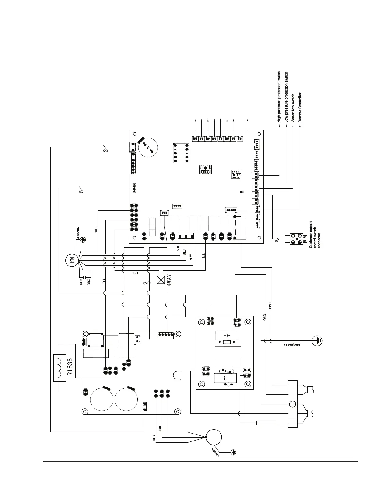
5. WIRING DIAGRAM
Crosswind 30-I, 40-I, 50-I
FUSE
Outlet water temp. sensor
CM
P1 P
2
Return gas
temp. sensor
Air temp. sensor
Heating coil pipe temp. s
ensor
Cooling coil pipe temp. sensor
Exhaust temp. sensor
Inlet water temp.
s
ensor
ACIN1
ACOUT1
LB
WU V
DC+
DC-
AC1
AC2
LA
G
DCFM
MDRV
OUT1A
AIN8
AC-N
WCTIL
DIN1 DIN2 DIN4
DIN5
AIN1
AIN2AIN3
AIN4
AIN5AIN6AIN7
+12V
B
ADIN3
OUT8A
OUT7
OUT6
OUT1
OUT8
DCHV
OUT9
T5A/250V
AC-L
RY2
S11
S16
S15
S14
S13
S12
CN12CN21
CN18
CN26
Electronic Expansion Valve
JP1
SW1
ACIN2
ACOUT2
PB18
Pump Control
YLW
BRN
BRN
BLU
YLW
YLW
BRN
BLU
BPH(C)N3 80.P-1.D
CN1
MA1.8K16
L2L
1
POWER
208-230V/60Hz
CL
CN24
CN19
CN6
BPH011(UK)
013094 700002
6100.64_Crosswind.indd 13 11/26/2019 4:16:44 PM