Control module STM 20 RED/DUO 3
B6_Control_SYS20_EN_V1.3.doc Art. Nr. 102-020401135 14 / 36
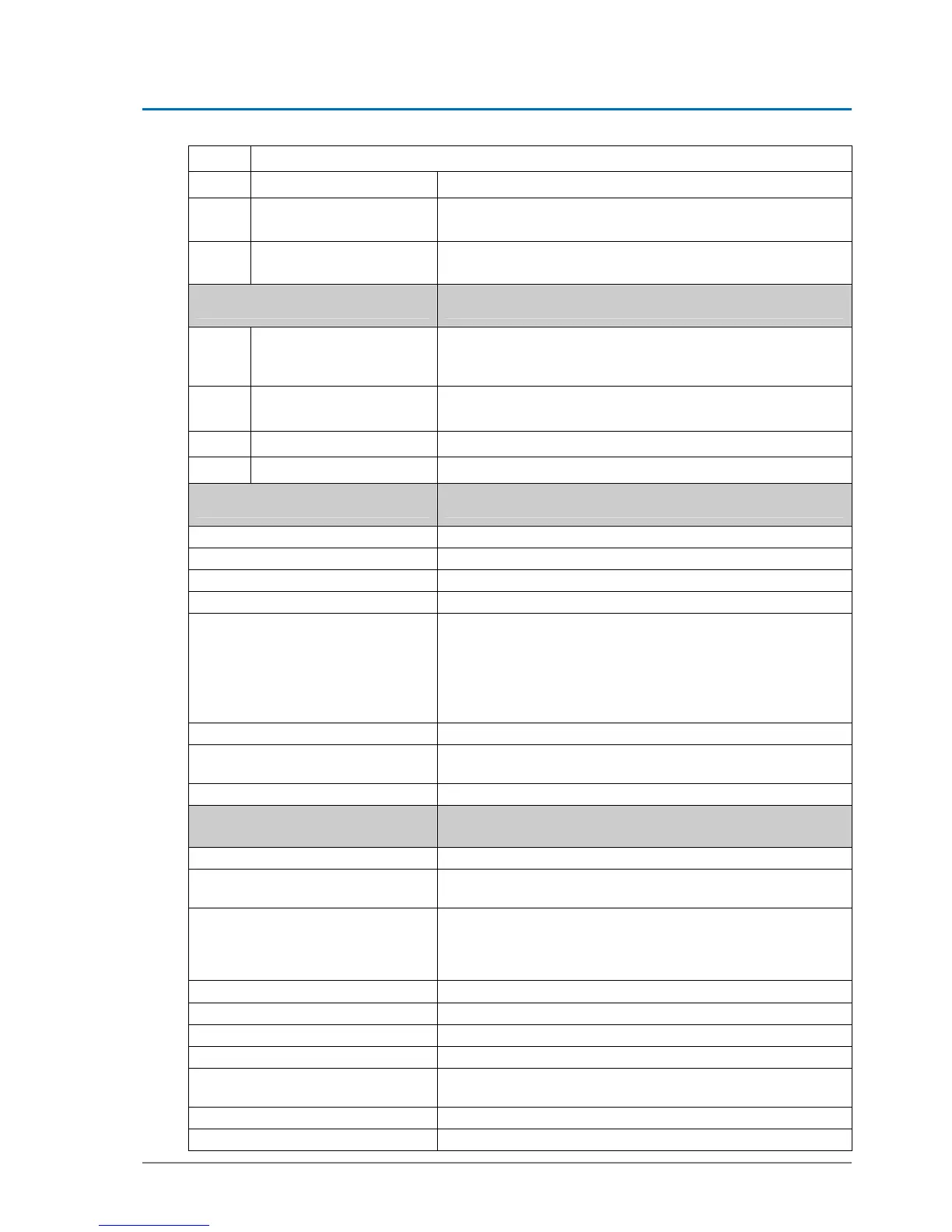
JP4 On RED and DUO installation
D-ST & EST-R Factory setting
EST-L
Fixing connecting clamp to upper part of toothed belt - Shunt
position remains unchanged !
JP5
Standard Master opera-
tion mode
Slave – only in case of two STM
Light-emitting diodes Meaning
LD1
Ground – red control-LED
Ground – must light up, if protective earth screw is with-
drawn
Otherwise grounding is on
LD2
green + 24 V
Is on, if 24 volt circuit OK
Comes off in case of by-pass in 24 volt circuit
LD3
green + 32 V
Is on, if system connected to mains voltage
LD4
red control-LED
For MF key S1 – is blinking, if button is pressed
Multifunctional key Function, after pulses have been given
1 pulse
Releases an opening movement (AKI)
2 pulses
Calibrating ELS
3 pulses
Calibrating door parameters
4 pulses
Entering programming level
5 pulses
RED
Redundancy test, if system connected to mains voltage
DUO
Battery emergency reaction, as long as system discon-
nected from mains
Battery test in case of mains connection
8 pulses
Loads default values of door type selected
9 pulses
Back to factory settings (afterwards emergency stop must be
actuated within 10 seconds)
14 pulses
Hardware reset is performed after approx. 12 seconds
Connector designation Connections
J1
Terminals 25 – 28 for BDE-D
J2
Terminals 1 – 12:
Functions according to wiring diagram 102-020110534
J3
Terminals 13 – 17 (only used with RED applications):
With DUO-applications the terminals 13 – 17 are used as
additional inputs
Functions according to wiring diagram 102-020110534
J4
Battery 1 (used for DUO and RED applications)
J5
Battery 2 (only used for RED applications)
J6
Locking
J7
Motor brake
J8
ATE motor 1 (The DUO-application can be driven with 1 mo-
tor only)
J9
ATE motor 2
J10
CAN bus / CAN sensors