Control module STM 22 RED/DUO 6
B6_Control_SYS20_EN_V1.3.doc Art. Nr. 102-020401135 32 / 36
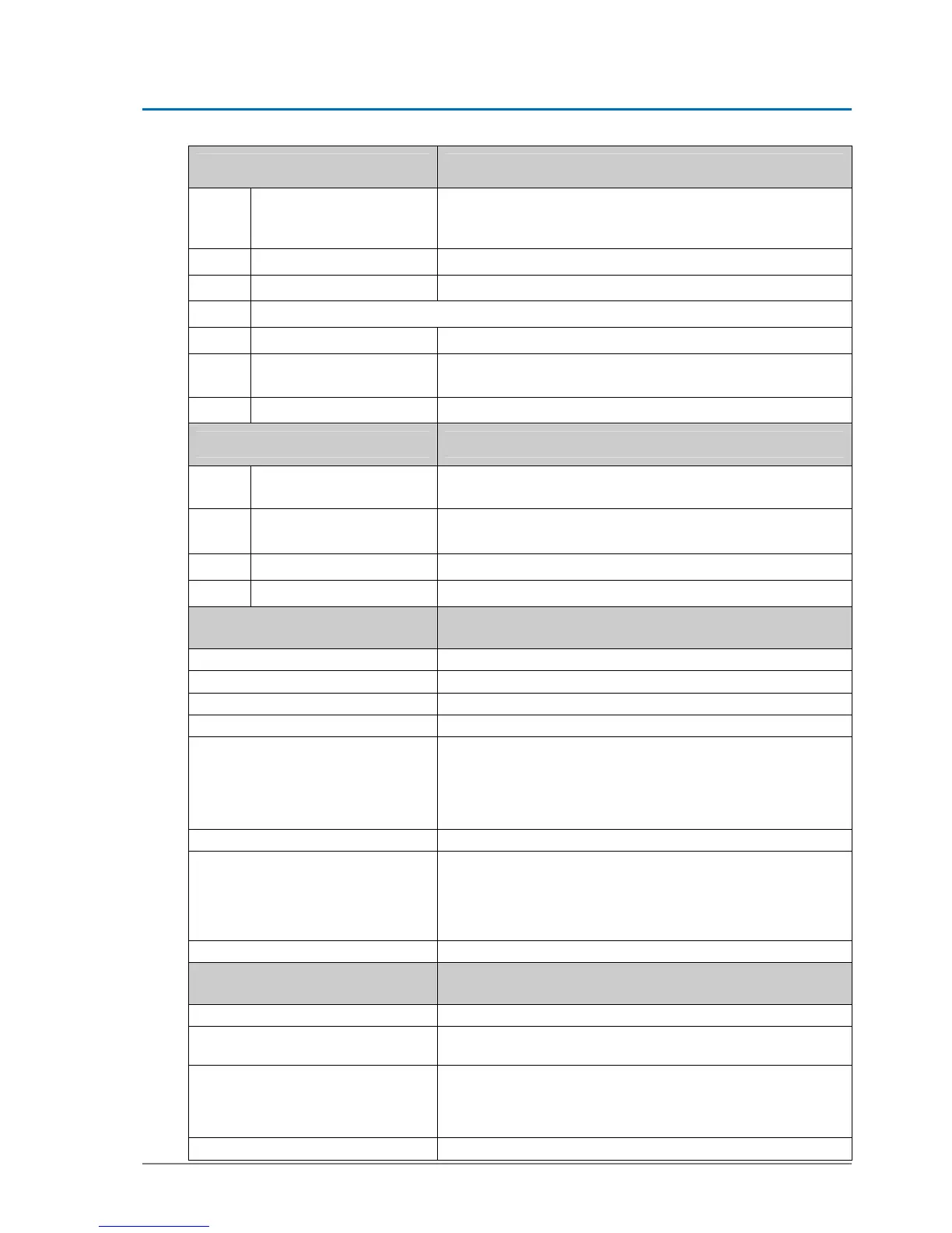
Jumper Change of function
JP1
Jumper on HEA
Allows emergency stop and HEA to be connected in series::
HEA 3-2
Emergency stop 2-1
JP2
Not equipped
JP3
Syst.-conditioned, internal Not visible – reserved for future applications
JP4 If used as RED+DUO-installation
D-ST & EST-R Factory setting
EST-L
Mounting of the belt clamp at the upper belt torsion – the
jumper-position remains unchanged!
JP5
Standard master mode Slave – only used with two STM
Light-emitting diode Meaning
LD1
Ground – Red control-
LED
Must light with distant ground screw
Otherwise, there is ground present
LD2
green + 24 V
Is on, if 24 volt circuit OK
Comes off in case of by-pass in 24 volt circuit
LD3
green + 32 V
Is on, if system connected to mains voltage
LD4
Red control-LED
For multifunctional key S1 – blinks when key is pressed
Multi function key Function, after impulses have been given
1 puls
Triggering the opening movement (AKI)
2 pulses
Calibrating ELS
3 pulses
Calibrating door parameters
4 pulses
Entering programming level
5 pulses
RED
Redundancy test with existing mains power
DUO
Battery emergency reaction, if no mains power available
Battery test with existing mains power
8 pulses
Loads default values of door type selected
9 pulses
Back to factory settings
(afterwards an emergency stop or a reset must be actuated
within 10 seconds) The function emergency-stop with reset
can only be actuated if the INPUT/OUTPUT parameter
Emergency-Stop with Reset is active!!
14 pulses
Hardware reset is performed within ca. 12 seconds
Connector designation Connections
J1
Terminals 25 – 28 for BDE-D
J2
Terminals 1 - 12:
Functions according to wiring diagram 102-020110533
J3
Terminals 13 – 17 (only used with RED applications):
With DUO-applications the terminals 13 – 17 are used as
additional inputs
Functions according to wiring diagram 102-020110534
J4
Battery 1 (use for DUO- and RED-applications)