EasyManua.ls Logo

red lion PAXR User Manual

red lion PAXR
16 pages
To Next Page IconTo Next Page
Page #1 background imageLoading...
Page #1 background image
GENERAL DESCRIPTION
The PAXR (PAX Rate Panel Meter) offers many features and performance
capabilities to suit a wide range of industrial applications. The optional Plug-in
Setpoint Alarm Cards allow the opportunity to configure the meter for alarms if
that is a requirement.
The PAXR meter accepts digital inputs from a variety of sources including
outputs from CMOS or TTL circuits and all standard RLC sensors. The
maximum input signal is 34 KHz.
The meter provides three different display indications. These include a Rate
Display, Max Display, and Min Display. Annunciators indicate which display is
being shown.
The front panel keys and three user inputs are programmable to perform
various meter functions. One of the functions includes exchanging parameter
lists, allowing double the number of programmable setpoint.
The meter can have up to four setpoint outputs, determined by the Plug-in
cards. The Plug-in cards provide dual FORM-C relays (5 A), quad FORM-A
relays (3 A) or either quad sinking or quad sourcing open collector logic
outputs. The outputs are assigned to the rate display value. The outputs can also
be independently configured to suit a variety of control and alarm requirements.
Once the meter has been initially configured, the parameter list may be
locked out from further modification entirely, or only the setpoint can be made
accessible. This lockout is possible through a security code or user input.
The meter has been specifically designed for harsh industrial environments.
With a NEMA 4X/IP65 sealed bezel and extensive testing to meet CE
requirements, the meter provides a tough yet reliable application solution.
SAFETY SUMMARY
All safety related regulations, local codes and instructions that appear in this
literature or on equipment must be observed to ensure personal safety and to
prevent damage to either the instrument or equipment connected to it. If
equipment is used in a manner not specified by the manufacturer, the protection
provided by the equipment may be impaired.
Do not use this meter to directly command motors, valves, or other actuators
not equipped with safeguards. To do so can be potentially harmful to persons or
equipment in the event of a fault to the unit.
SPECIFICATIONS
1. DISPLAY: 5 digit, 0.56" (14.2 mm) red LED
2. POWER:
AC Versions (PAXR0000):
AC Power: 85 to 250 VAC, 50/60 Hz, 12 VA
Isolation: 2300 Vrms for 1 min. to all inputs and outputs. (300 V working)
DC Versions (PAXR0010):
DC Power: 11 to 36 VDC, 7 W
AC Power: 24 VAC, ± 10%, 50/60 Hz, 9 VA
Isolation: 500 Vrms for 1 min. to all inputs and outputs (50 V working)
3. SENSOR POWER: 12 VDC, ±10%, 100 mA max. Short circuit protected.
4. ANNUNCIATORS:
! - Rate
" - Maximum (High) Rate
# - Minimum (Low) Rate
SP1 - Setpoint 1 Output State
SP2 - Setpoint 2 Output State
SP3 - Setpoint 3 Output State
SP4 - Setpoint 4 Output State
5. KEYPAD: 3 programmable function keys, 5 keys total.
6. RATE DISPLAY:
Accuracy: ± 0.01%
Minimum Frequency: 0.01 Hz
Maximum Frequency: 34 KHz
Maximum Display: 5 digits: 99999
Adjustable Display (low) Update: 0.1 to 99.9 seconds
Over Range Display: “r OLOL”
1
MODEL PAXR-1/8 DIN RATE PANEL METER
! 5-DIGIT LED DISPLAY
! RATE INDICATION
! PROGRAMMABLE FUNCTION KEYS / USER INPUTS
! FOUR SETPOINT ALARM OUTPUTS (W/Plug-in card)
! NEMA 4X/IP65 SEALED FRONT BEZEL
CAUTION: Read complete
instructions prior to installation
and operation of the unit.
CAUTION: Risk of electric shock.
DIMENSIONS In inches (mm)
Note: Recommended minimum clearance (behind the panel) for
mounting clip installation is 2.1" (53.4) H x 5.0" (127) W.
Bulletin No. PAXR-A
Drawing No. LP0511
Released 7/01
Tel +1 (717) 767-6511
Fax +1 (717) 764-0839
www.redlion-controls.com
UL Recognized Component,
File # E179259
Question and Answer IconNeed help?

Do you have a question about the red lion PAXR and is the answer not in the manual?

red lion PAXR Specifications

General IconGeneral
Brandred lion
ModelPAXR
CategoryMeasuring Instruments
LanguageEnglish

Summary

General Description and Specifications

Display Specifications

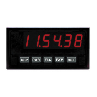
Details the 5-digit, 0.56" red LED display characteristics.

Power Specifications

Covers AC and DC power requirements, including isolation specifications.

Input and Output Capabilities

Describes Input A, User Inputs, and available Setpoint Output Cards.

Certifications and Compliance

Lists safety, EMC certifications, and compliance standards for the meter.

Ordering Information

Meter and Plug-in Card Models

Provides model numbers and descriptions for the meter and optional plug-in cards.

Meter Installation

Panel Mounting Instructions

Instructions for preparing the panel cutout and mounting the meter securely.

Installation Environment Guidelines

Guidelines for selecting an installation location and cleaning the unit's bezel.

Setting Jumpers and DIP Switches

User Input Jumper Configuration

Explains how to set the user input logic jumper for proper operation.

Input Signal DIP Switch Settings

Details how to configure DIP switches for Input A settings like frequency and logic.

Installing Optional Plug-in Cards

Static Discharge Precautions

Precautions for handling static-sensitive components during card installation.

Quad Sourcing Output Card Installation

Specific instructions for installing the PAXCDS40, including jumper settings.

Wiring the Meter

General Wiring Overview

General guidelines for electrical connections using screw-clamp terminals and wire types.

EMC Installation Best Practices

Recommendations for minimizing electromagnetic interference during installation.

Power and User Input Wiring

Diagrams for AC/DC power wiring and user input connections for sinking/sourcing logic.

Input Signal Wiring Examples

Illustrates various input wiring configurations for different signal sources.

Setpoint Alarm Wiring

Wiring diagrams for dual relay, quad relay, and open collector setpoint cards.

Front Panel Operation

Display Mode Navigation

Explanation of how to navigate display modes using the DSP and PAR keys.

Programming Key Functions

Describes how to use function keys for programming and parameter adjustments.

Programming the Meter

Entering and Exiting Programming Modes

How to enter and exit the meter's programming modes (Full and Quick).

Navigating Programming Modules

Explains how to navigate through the five programming modules using keys.

Parameter Value Selection and Entry

Details the process of selecting and entering parameter values using arrow and PAR keys.

Display Control Functions

Functions for advancing, storing, resetting, and inhibiting displays.

Setpoint Control Functions

Functions for deactivating, holding, and resetting setpoint states.

Module 3: Display and Program Lock-out

Display Lock-out Settings

Configures visibility of Rate, Max, and Min displays (rEd, LOC).

Program Lock-out Settings

Manages access to programming modes via security code or user input (PLOC).

Module 4: Rate Input Parameters

Display Update and Rounding Settings

Configures low/high update times and rate display rounding.

Rate Scaling and Input

Sets rate decimal position, scaling display, and scaling input values.

Cut-out and Capture Delay Settings

Adjusts low cut-out, max capture delay, and min capture delay times.

Rate Input and Scaling Details

Rate Display Exceeded Condition

Behavior when the rate display exceeds its 5-digit capacity ('OLOL').

Rate Scaling Calculation Methods

Explains key-in and applied methods for scaling rate display values.

Input Frequency Calculation Process

Describes how the meter calculates input frequency based on falling edges.

Module 6: Setpoint (Alarm) Parameters

Setpoint Select and Annunciators

Selects setpoints and configures annunciator display modes (OFF, Normal, Flash).

Setpoint Output Logic and Power Up State

Configures output logic (Normal/Reverse) and power-up state (Save, OFF).

Setpoint Action and Value

Defines setpoint actions (Timed Out, Boundary, Latch) and setspoint values.

Setpoint Parameter Configuration

Setpoint Tracking and Boundary Type

Sets how setpoint values track other selections and defines boundary types.

Setpoint Hysteresis and Delays

Configures hysteresis, off delay, on delay, and time-out for setpoints.

Module 9: Factory Service Operations

Restore Factory Defaults

Instructions to restore factory default settings and handle power-up errors.

Troubleshooting and Parameter Summary

Troubleshooting Common Problems

Lists common issues like no display, locked out, incorrect values, and their remedies.

Parameter Value Chart

A summary table of user input, rate, lock-out, and setpoint parameters with factory settings.

Related product manuals