32
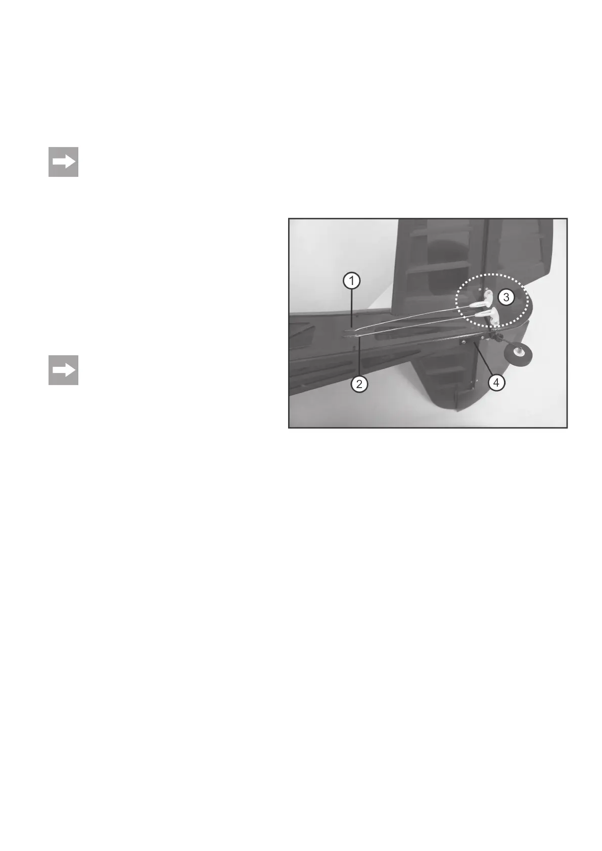
h) Mounting the Rudder Horns to the Rudders and Elevators
Sketch the installation site of the rudder horns to the elevators in a straight line from the linkage exit of the elevator linkage.
Observe that the linkage rods for the elevator in the rear area of the fuselage are guided out of the fuselage by the upper slots (figure 6, item 1). Drill the
corresponding holes with a matching drill (as already done for the ailerons). The rudder horns can now be mounted (figure 6, item 3).
The rudder linkage is guided out of the lower slot in the left area of the elevator linkage (viewed from behind in flight direction) (figure 6, item 2). Again, the
installation site of the rudder horn must be determined according to a straight line from the slot to the rudder and the rudder horn must be installed there (as
shown for the aileron and elevator).
To prevent breaking out of the drilled holes, slowly drill in at a right angle and with a hard wood base as a counterbearing. For best results, we
recommend drilling with 0.1 mm below the size.
i) Mounting the Tail Spur with Linkage
The tail spur must be firmly glued to the rudder.
For this, you need to drill the corresponding hole into the rudder so that
the end of the assembly plate rests against the rudder at the turning
point
A few drops of superglue must be put into the rudder hole with the tail
spur disassembled to make the wood more stable.
As shown in figure 6, item 4, the assembly plate of the tail spur then
must be screwed to the fuselage and the wheel must be mounted.
Mark and drill the corresponding holes into the fuselage and screw the
assembly plate on with grub screws 2.5 x 10 mm.
For better seat, we recommend putting a drop of superglue
into the screw holes of the assembly plate.
The spur gear linkage is performed by the rudder linkage since they
are already firmly connected.
The spur gear is attached to the tail spur with adjustment rings. Screw
connections metal/metal without stop nuts must be secured with
threadlocker varnish.
Figure 6