34
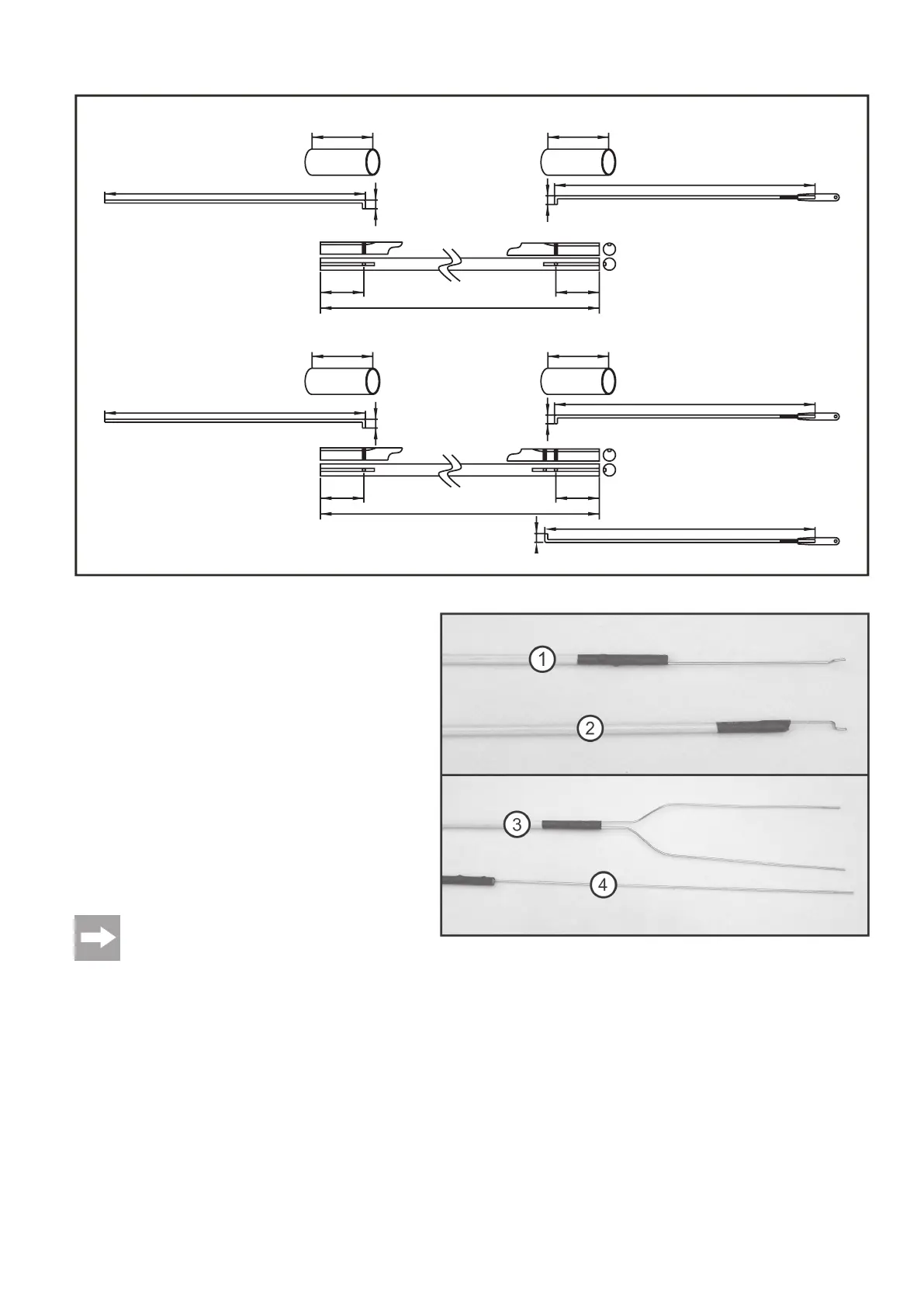
l) Creating the Linkage Rods
The linage rods must be built from parts of the construction kit for linkage
of the elevators and rudders. The length indications are shown in figure
9a.
To create the linkage, the shortened wires must be bent by 5 mm at a
90° angle at the end as shown in figure 9a and glued to the wood thrust
rods with 30-minute epoxy resin.
For this, the rods first need to be fastened with a drop of superglue.
Then wrap a fine thread around the fastened thrust rod several times.
Then the epoxy resin is applied and the entire unit is sealed with a
shrink hose.
The rods then need to be bent to match. Figure 9b shows The finished
elevator linkage rods for connection to the servo rudder horns in item 1
and the rods for the rudder in item 2.
For connection to the rudder horns of the tail units, item 3 shows the
rods for the elevator and item 4 those for the rudder.
If you have equipped your model with a combustion engine,
you need to adjust and install the linkage rods for the
carburettor settings as required depending on the
carburettor linkage of the combustion engine.
The construction kit includes the corresponding material,
which may, however, have to be supplemented or placed
by your own or additionally purchased material.
35
35
35
35
230
230
235
350
350
150
150
25
25
25
25
5
5
5
5
5
Figure 9b
Figure 9a