Rev 19 Page47
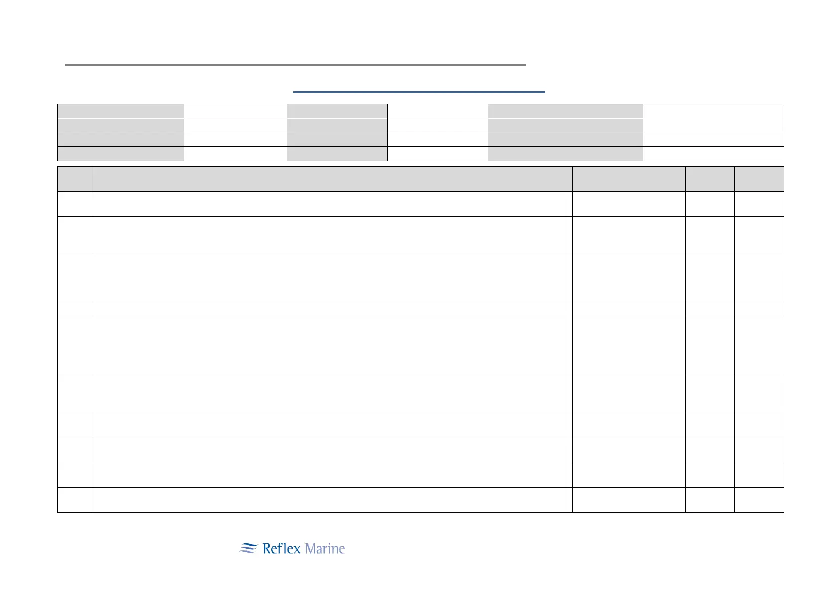
Post Load Test Visual Inspection Checklist Form
Avg No of Transfers / Year
Original Inspection record filed in
Main Lift-Eye Plug (Critical Part)
Visually inspect in situ for any signs of wear, cracks, deformation or other damage
Main Lift-Eye Plug M16 Bolts (Critical Part)
Visually inspect the two M16 lifting eye bolts, nuts, split pins and tamper proof seals that connect the main lift-eye
plug to the central column for wear or damage.
M48 Keel Boss and M10 Cross Bolt (or roll pin on older models) (Critical Part)
At the bottom end of central column, visually inspect the M48 keel boss nut and ensure that the M10 cross bolt
(keel plate nut roll pin on older models) is secure c/w split pin & tamperproof seal. Check the presence of anti-
rotation fittings and that all bolts are secure. Do not go underneath an active lift.
Backup-Eye - Visually inspect for any wear or damage and check that the split pin and tamper proof seal are intact.
Main Seat Spring Check
Check the spring condition and test the operation of the spring.
1. In-situ check The Frog-3 Sliding Sleeve Cross Bolt Runner should rest against the slotted Sliding Sleeve,
with a pre-compression force of approximately 60kg. If a space exists between the slot edge
and the Cross Bolt Runner greater then 13mm, the Spring should be replaced.
Sliding Sleeve and Alignment Cross Bolt
Inspect the alignment cross bolt, check for any deformation of the bolt. Check that the nylon bushings are in good
condition (anti-rotation roll pin on older models) – Note: This is a special high yield strength bolt.
Landing Feet - Examine the feet to ensure that they are in good condition after the load test. The feet will normally
recover full height sometime after the load test weight is relived.
Seat Base Assembly - Visually inspect for any wear or damage and ensure that all bolts’ and other fasteners are
fully secure.
Frame and Buoyancy - Visually inspect for any damage and ensure that all bolts and fasteners are tight and fully
secure.
Inspection Data Plate - Check the date of the last examination/inspection has been correctly inserted and is
indelibly legible.