Rev 19 Page30
5.12 Stretcher Mode
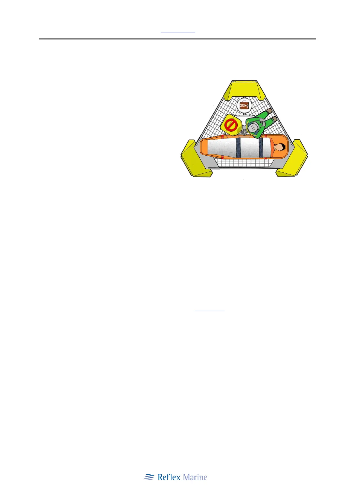
5.12.1 Converting FROG-3 to Stretcher Mode (Figure 7)
It is recommended that the procedure be
conducted by two or three persons. This is to
ease handling of the lower buoyancy blocks
which weigh approximately 20 kg. The
procedure should not be conducted over
grated flooring to prevent the risk of small
fittings falling through the floor. The procedure
should be conducted with a clear area around
FROG-3 to provide space for realignment of the
buoyancy units.
Figure 7: Stretcher Mode Arrangement
Tools Required
i. 6 mm Hex Key (for M10 bolts - Seat, Stretcher Frame).
ii. 8 mm Hex Key (for M12 bolts - Buoyancy).
iii. 17 mm Wrench (for M10 bolts - Seat).
iv. 19 mm Wrench (for M12 bolts - Luggage Box).
v. Box / Bag for Loose Fittings.
vi. FROG-3 Diagrams.
5.12.2 Stretcher Mode Conversion Procedure
i. Refer to Figure 8: Buoyancy Reconfiguration Diagram.
ii. If the optional luggage box has been fitted (see Appendix E) unscrew the 4 x M12 Hex Bolts
and remove from the lower buoyancy.
iii. Luggage nets may remain in place to speed up the conversion or remove to store.
iv. Remove the bolts (4 x M12 Dome Cap) and spacers from lower buoyancy blocks B and C.
Note: The latest FROGs do not have spacers P/N F-01-048 between the lower buoyancy modules and the frame.
v. Fix lower buoyancy units B and C to outside of unit. Tighten the M12 dome cap bolts to hand
tight with hex key (Max 18 NM).
Note: Over-tightening of these bolts can lead to damaged buoyancy.
 Loading...