Rev 19 Page32
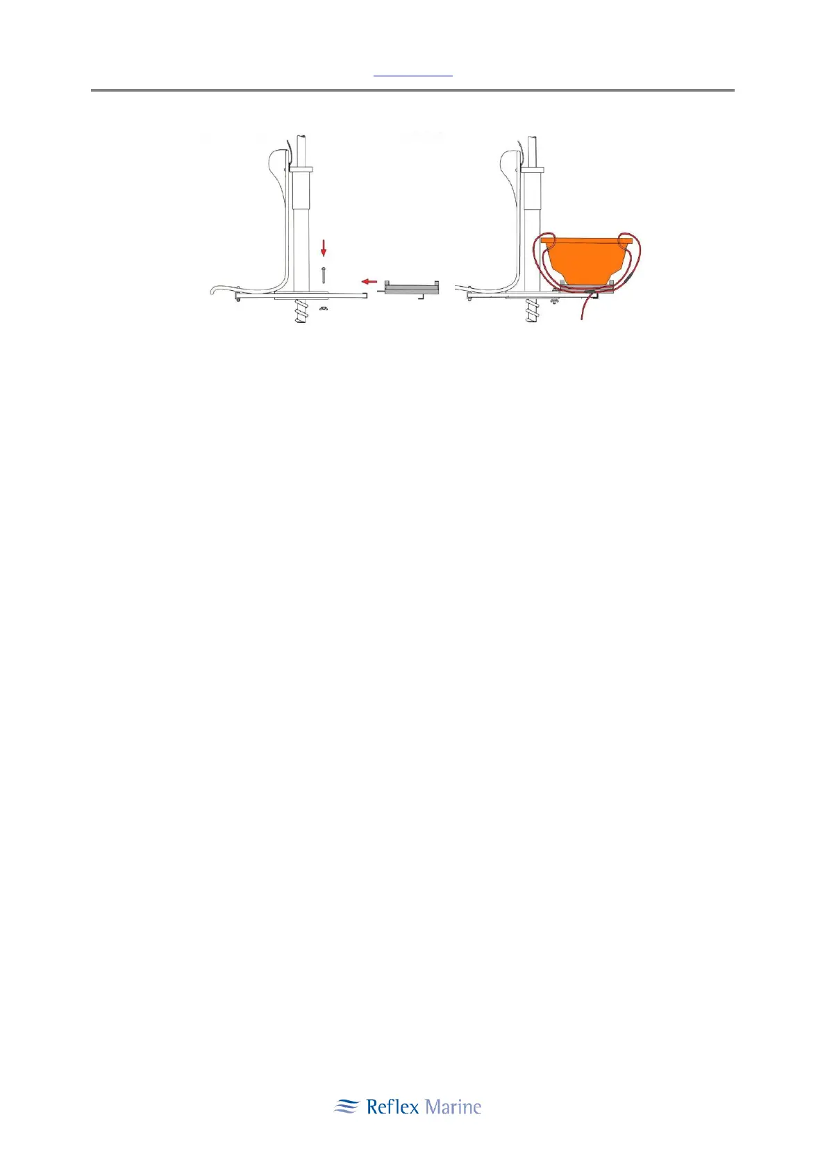
Figure 9: Stretcher Fitting Diagram
5.12.3 Positioning the Stretcher
i. Complete the ‘Converting to Stretcher Mode’ procedure.
ii. Ensure the stretcher casualty is securely strapped into the stretcher.
iii. Using three persons to lift the stretcher (two either side at shoulders, one at feet), move
stretcher head first through door B - C (door opening with stretcher frame)
Note: Observe safe manual handling practice when lifting the stretcher.
iv. Place the head-end of the stretcher on to the stretcher frame and slide the stretcher into
position as per Figure 7: Stretcher Mode Arrangement.
v. An intravenous drip may be placed on the hook* on the central column. (*where fitted)
vi. Secure the stretcher in position with the two straps provided as shown in Figure 9 Stretcher
Fitting Diagram:
a. Begin by feeding the fork end of the strap through eyelets on the stretcher frame
then through closest handles of the stretcher and continue around through to the
second stretcher handle.
b. Fasten underneath.
c. Ensure the stretcher is secure.
vii. Only one passenger should accompany the casualty.
5.12.4 3-Seat Mode Conversion Procedure
i. Refitting the seat is the reverse of the conversion to stretcher mode.
ii. Tighten the fittings for the lower buoyancy unit and the seat to low torque hand tight only
(18 NM). Over-tightening of these bolts can lead to damage to the buoyancy inserts or to
the seat.