05.11.21920-191
G800C
1
FAN WALL CONTROL INSTALLATION KIT
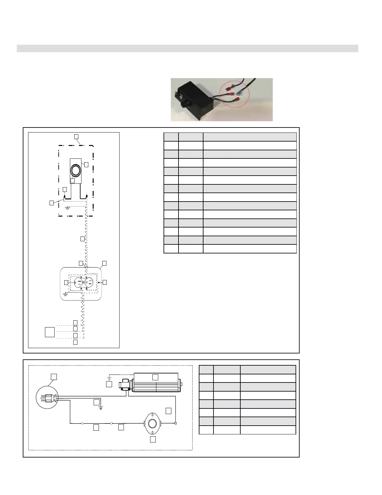
1. Connect the supplied speed control switch and unit receptacle to
the 120V mains power supply by following the wiring diagram as
shown.
The fan may be instaled with the optional Wall Control Kit (761-
974), which allows the fan speed control module located inside the
unit to be replaced by a wall mounted fan speed control.
WALL CONTROL KIT MUST BE INSTALLED DURING UNIT
INSTALLATION STAGE.
2. Remove the fan speed control module from the fan kit by breaking
the connection of the wires at the connectors shown below. Dis-
card the fan speed control module.
Item Part No. Description
1 911-159 Power Cord
2 910-692 Green Ground Wire
3 911-290/P Fan
4 911-240 Brown Connector Cable
5 910-811 Black Wire
6 910-142 Fan Thermodisc
7 910-896 Black Wire
Item Part No. Description
1 910-367 Junction Box
2 910-412 Speed Contron Switch w/Lead Wires
3 910-417 White Knob
4 N/A Wire Nuts
5 910-366 White Faceplate
6 N/A 14 AWG Wire*
7 910-687 Wire Clamp
8 910-429 Receptacle Box Inside Stove
9 910-428 Receptacle (dedicated use by stove fan)
10 N/A Copper Ground Wire*
11 N/A White Wire (Neutral)*
12 N/A Black Wire (Hot)*
13 N/A 14 AWG Wire*
 Loading...