8
Manual CORRIGO U-SERIE 2002-09
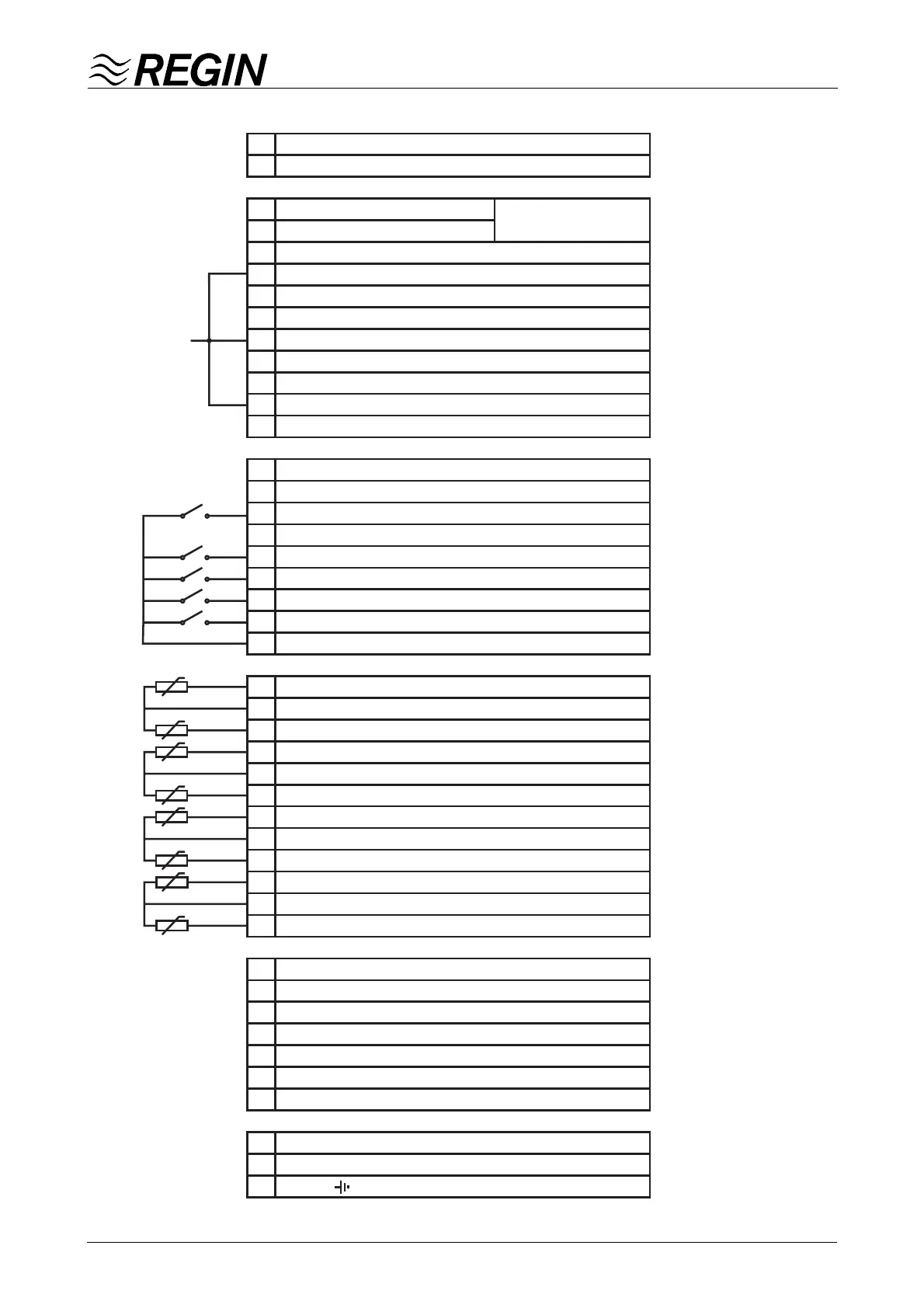
Wiring diagram U20
1
2
3
4
5
6
7
8
9
10
11
12
13
14
15
16
17
18
19
20
21
22
23
24
25
26
27
28
29
30
31
32
33
34
35
36
37
38
39
40
41
42
43
44
Net A LON-connection U20-LON only
Net B LON-connection U20-LON only
DO7 Alarm output
DO7 Alarm output
DO6 3p. outp. HS2-CV1 - decrease / TO1
24 V AC in DO5/DO6
DO5 3p. outp. HS2-CV1 - increase / TU2
DO4 Control Pump HS2-P
24 V AC in DO3/DO4
DO3 3p. outp. HS1-CV1 - decrease
DO2 3p. outp. HS1-CV1 - increase
24 V AC in DO1/DO2
DO1 Control Pump HS1-P
DI8 Not connected
DI7
Not connected
DI6 Monitor pump HS2-P
DI5
Not connected
DI4 External alarm
DI3 Alarm expansion vessel
DI2 Monitor pump HWC-P
DI1 Monitor pump HS1-P
Common DI1-DI8
AI1 Temperature outdoor
Signal neutral
AI2 Temperature HS1 Outgoing
AI3 Temperature HS1 Room / HWC
Signal neutral
AI4 Temperature HS1 Return / HP1 Tillopp
AI5 Temperature HW Outgoing / HP1 Return
Signal neutral
AI6 Temperature THW Outgoing
AI7 Temperature HS2 Outgoing
Signal neutral
AI8 Temperature HS2 Room / HS2 Return
AO1 HS1-CV1 0...10 V DC
AO2 HW-CV1 / THW-CV1 0..10 V DC
AO3 THW-CV1 / THW-CV2 0..10 V DC
AO4 HS2-CV1 0...10 V DC
AO5 HS1-CV2 0...10 V DC
AO6 HS2-CV2 0...10 V DC
Signal neutral for AO1-AO6
G Supply voltage 24 V AC
G0 System neutral
Earth
1A
24 V AC/DC
24 V AC
 Loading...