Do you have a question about the Regin Corrigo U10 Series and is the answer not in the manual?
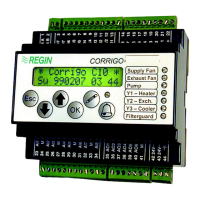
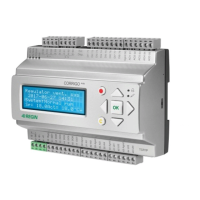
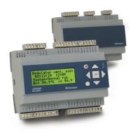
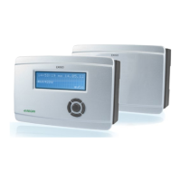
Introduces the CORRIGO U-series controllers for HVAC systems.
Compares features, I/O, and technical specifications of U10 and U20 models.
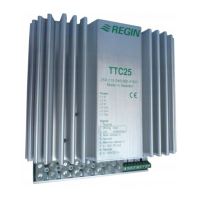
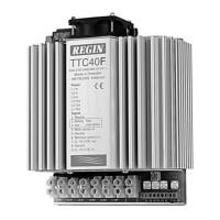
Details electrical, environmental, and physical specifications for CORRIGO controllers.
Details the specific analogue and digital inputs and outputs for the U10 model.
Details the specific analogue and digital inputs and outputs for the U20 model.
Guides the user through the physical installation and electrical wiring of the CORRIGO unit.
Provides a visual representation of terminal connections for the U10 model.
Provides a visual representation of terminal connections for the U20 model.
Explains the function and configuration of each analogue input for temperature sensors.
Describes the purpose and wiring of digital inputs for status and alarm signals.
Explains the use of analogue outputs for controlling actuators with 0-10V signals.
Details the functions of digital outputs, including pump control and alarm signals.
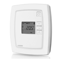
Explains the operation of each button on the CORRIGO front panel for menu navigation and control.
Outlines the main menu structure and how to navigate through its options.
Details how to view, understand, and acknowledge active alarms.
Describes user login procedures and how to manage access codes.
Explains the use of configuration codes and refers to tables detailing parameter options.
Details the configuration options for analogue inputs Al1 through Al6.
Covers configuration for inputs Al7-Al8, night setback, and room compensation.
Details configuration for HS2, HW/THW circuits, and pump control logic.
Describes settings for setpoints, outputs, and control curves for HS1.
Details configuration for HS2, HW/THW circuits, and analogue input adjustments.
Details the configuration of analogue and digital outputs and manual setting procedures.
Covers setting the clock, periods, holidays, and timer outputs.
Details temperature deviation alarms and how to suppress the alarm output.
Covers system settings, LED functions, and parameter storage.
Lists the factory default configuration codes and parameter mappings for U10 and U20 models.
Records commissioning settings for U10 configuration, HS1, and HW/THW controls.
Records commissioning settings for scheduler and alarm parameters for the U10.
Records commissioning settings for U20 configuration, HS1, and HS2 controls.
Records commissioning settings for scheduler and alarm parameters for the U20.
Provides a detailed mapping of configuration code digits to U10 parameters A through L.
Provides a detailed mapping of configuration code digits to U10 parameters M through V.
Provides a detailed mapping of configuration code digits to U20 parameters A through L.
Provides a detailed mapping of configuration code digits to U20 parameters M through V.
| Storage temperature | -40 to +70°C |
|---|---|
| Protection class | IP20 |
| Digital inputs | 4 |
| Analog inputs | 4 |
| Analog outputs | 2 |
| Number of universal inputs | 4 |
| Number of relay outputs | 2 |
| Analog output range | 0-10 V DC |
| Relative humidity | Max 90% RH, non-condensing |
| Communication | Modbus RTU |
| Input types | Pt1000, 0-10 V, dry contact |