24
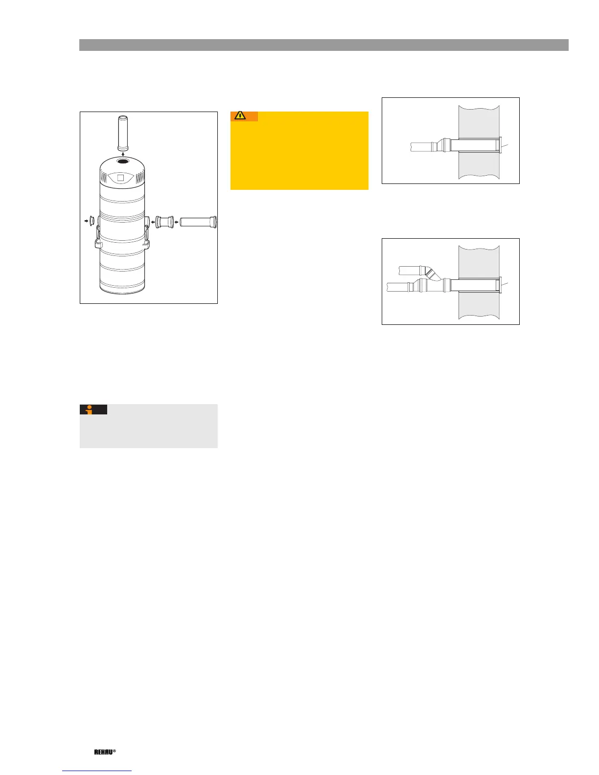
Connecting DN 50 suction pipe
Fig. 5-20: Connecting suction and exhaust
air pipe
➜ Route suction pipe (RAUPIANO Plus
DN 50) to left or right-hand connection
port.
➜ Directly connect suction pipe to central
vacuum unit with a double socket
(included).
➜ Close off unused connection port with
dummy plug (included).
Connecting DN 75 exhaust air pipe
The exhaust air is discharged into the open
via exhaust air silencers.
■ Keep pipe length as short as possible and,
wherever possible, do not use any 87°
bends.
■ Choose a suitable site for positioning the
exhaust air vent that leads into the open
(e.g. not on patios)
➜ For unit types 2000 and 3000, route
exhaust air pipe (RAUPIANO Plus DN 75)
to the exhaust air port on the central
vacuum unit (see Fig. 5-23).
➜ For unit type 4000, route two exhaust air
pipes (RAUPIANO Plus DN 75) to the
exhaust air port on the central vacuum unit
(see Fig. 5-24).
➜ Install an exhaust air silencer in each
exhaust air pipe between the central
vacuum unit and the wall duct (see
Fig. 5-23 and Fig. 5-24).
➜ For unit types 2000 and 3000, connect the
exhaust air pipe (DN 75) to the wall duct
(DN 110) via an adapter (see Fig. 5-21).
➜ For unit type 4000, connect both exhaust
air pipes (DN 75) to the wall duct (DN 110)
via a connector (see Fig. 5-22).
➜ Fit an external air vent to the side of the
wall duct that leads into the open.
Fig. 5-21: Wall duct for
unit types 2000 and 3000
1 External air vent
Fig. 5-22: Wall duct for
unit type 4000
1 External air vent
If two riser pipes are used, you can
connect the suction pipes to the left and
right-hand connection ports.
DN 50
DN 75
Caution!
Damage to property!
Backup of exhaust air in the central
vacuum unit can cause damage to
property.
➜ Install exhaust air pipes with a gradient
of at least 2% to the external air vent.
DN 75
DN 110
1
DN 75
DN 75
DN 110
1
 Loading...