13900-103 Rev. A Page 15
Testing (Continued)
LCD Brightness Adjustment
This procedure details the adjustment of the brightness for
the LCD backlight. This adjustment is located on the
Power Input / Output Board (Fig.7,27) (citcuit board on
bottom of unit). Refer to Table 1 for the voltages required
at TP9. To determine which LCD you have and are
replacing, refer to Figures 1 and 2.
1. Apply the +probe of a digital voltmeter to TP9 on the
bottom circuit board and the –probe to pin 5 of the
RS232 connector located next to the input power
connector.
2. Adjust R1 until the voltage at TP9 is set as indicated
in Table 1 while referencing the correct LCD Assem-
bly.
3. Apply one small drop of enamel paint (e.g., nail polish)
to the top of R1 so that it will not be moved acci-
dently.
LCD Contrast Adjustment
This procedure details the adjustment of the LCD contrast
control on the Power Input / Output Board. Refer to Table
1 for the voltages required at the test points (TP). To
determine which LCD you have or are replacing, refer to
Figures 1 and 2.
1. Adjust the external contrast knob near the RS232
connector to mid-range.
2. Apply the +probe of a digital voltmeter to TP2 on the
bottom circuit board and the -probe to pin 5 of the
RS232 connector located next to the input power
connector.
3. Adjust R20 until the voltage at TP2 is set as indicated
in Table 1 while referencing the correct LCD Assem-
bly.
4. Apply one small drop of enamel paint (e.g., nail polish)
to the top of R20 so that it will not be moved acci-
dently.
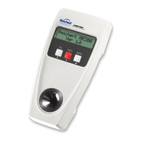
Figure CT-15. LCD P/N 13960-966
Note: The 13960-966 has a different circuit board than
that of the 13920-947 and the 13960-945.
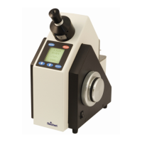
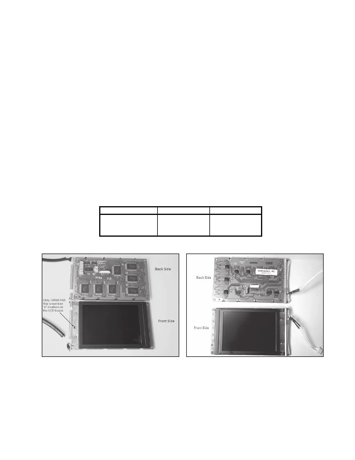
Figure CT-14. LCD P/N 13920-947 or 13960-945
Note: The 13960-945 has a “6” marked on the bezel,
however, the 13920-947 does not have a “6”
marked on the bezel. The 13920-947 and the
13960-945 circuit boards are the same.
Table 1. Test Point Voltages
LCD Part Number TP9 (R1) TP2 (R20)
13920-947 0.75 VDC -20.5, ±0.1 VDC
13960-945 0.85 VDC -19.6, ±0.1 VDC
13960-966 0.85 VDC -18.0, ±0.2 VDC
 Loading...