Page 40 13900-103 Rev. A
General Assembly
General assembly of the unit requires assembling the
outside covers and the top of the tonometer head to the
unit. Perform the following steps in the order given.
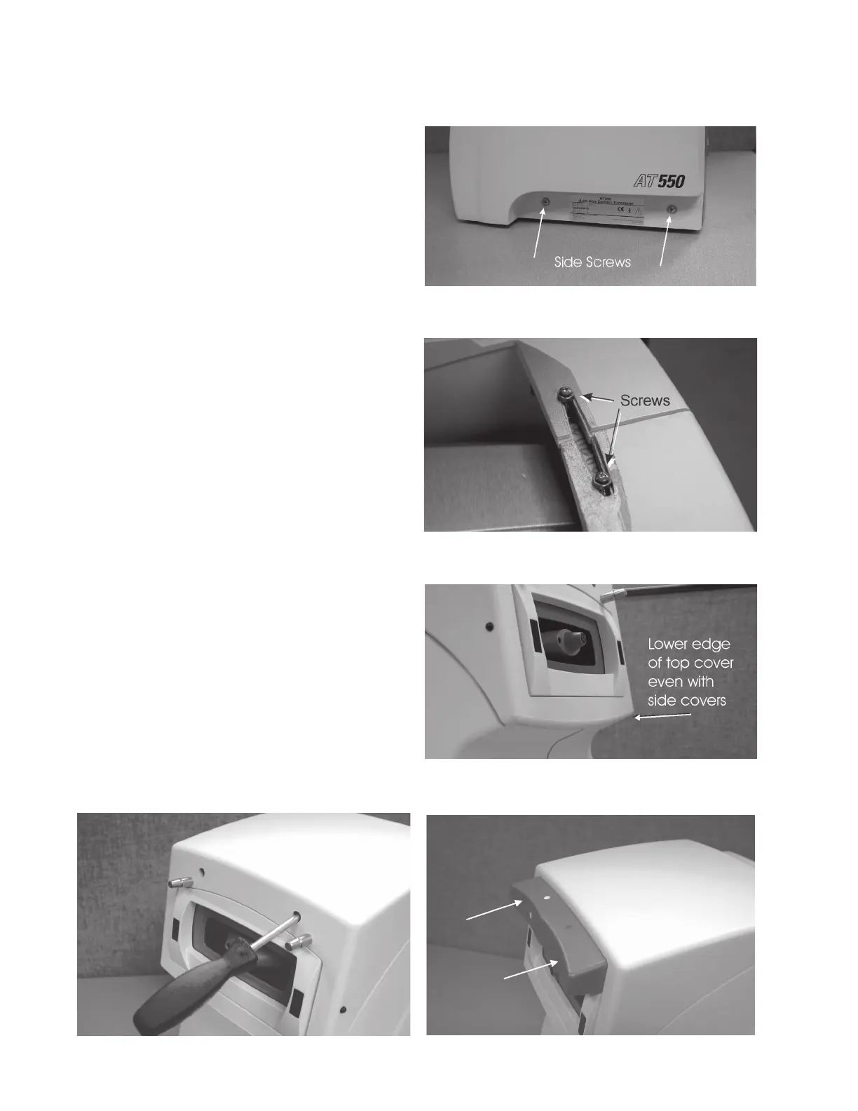
1. Install one of the side covers and secure it with the
bottom side screws. Refer to Figure AS-1.
2. Install the other side cover and secure it with the
bottom side screws. Refer to Figure AS-1.
3. Install the upper side cover screws on the operator's
side of the unit and secure both side covers. Refer to
Figure AS-2.
4. Tighten the top screws on the patient's end to secure
the bracket to the side covers.
5. Attach the Left/Right detector harness to its mating
connector and slide the wires into its retaining clip
located on the side cover.
CAUTION: DURING ASSEMBLY, ENSURE THAT THE LEFT/
RIGHT DETECTOR HARNESS IS INSTALLED INTO
THE HARNESS CLIP AND THAT THE UNUSED
LENGTH OF WIRE DOES NOT EXTEND IN FRONT OF
THE ALIGNMENT WINDOWS ON THE REAR MASK
OR THE UNIT MAY LOOK FOR AND NOT FIND THE
EYE DURING A MEASUREMENT.
6. Install the top cover onto the instrument so that the
lower front edge of the top cover is even with the
lower edge of the opening on the patient's end of the
side covers. Refer to Figure AS-3
7. Insert a Phillips #2 screwdriver into the access holes
and turn the screws clockwise to 10.0 lbf·in (1.1 N·m)
secure the top cover to the unit. Refer to Figure AS-4.
8. Push the the headrest evenly onto the mounting posts.
Refer to Figure AS-5.
Figure AS-5. Headrest Installation
Figure AS-4. Top Cover Screws Installation
Figure AS-1. Lower Side Cover Screws
Figure AS-2. Upper Side Cover Screws
Figure AS-3. Top Cover Alignment
 Loading...