Page 26 13900-103 Rev. A
Optical Alignment
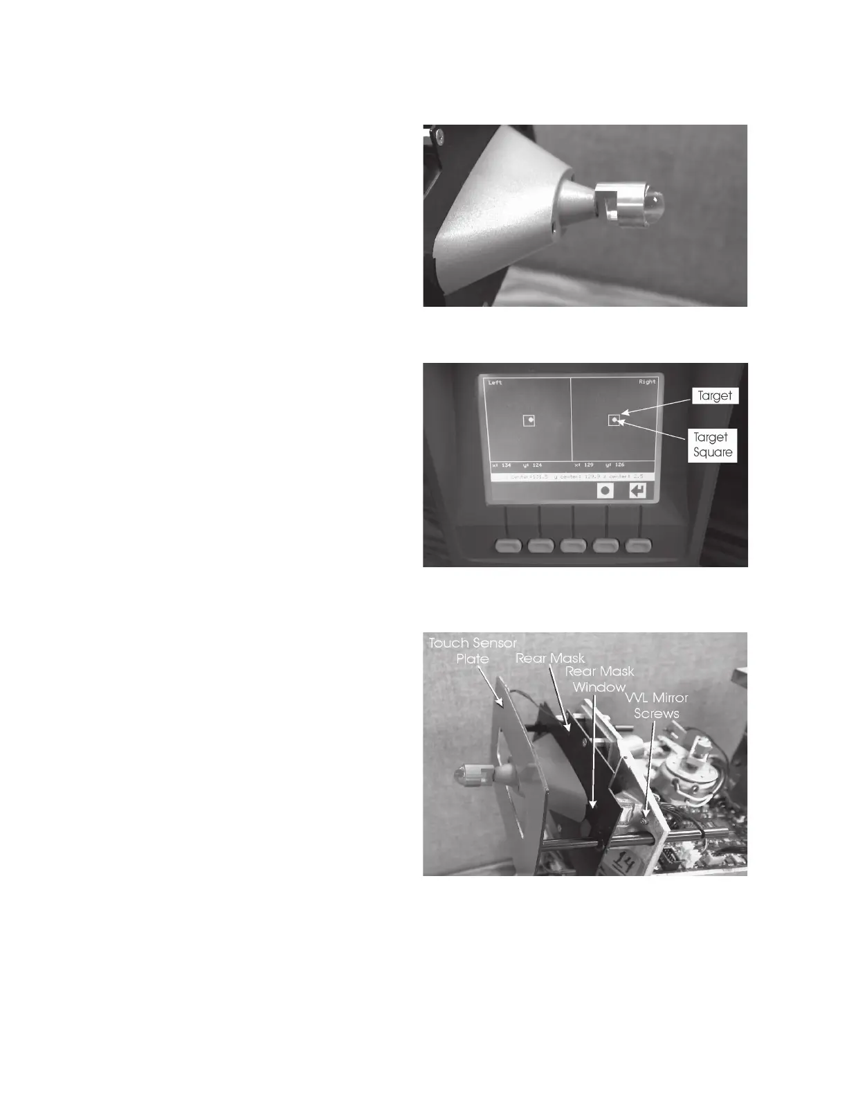
This test displays the optical alignment of the measuring
system. When the square dots, representing the VVL
cameras, are within the borders of the target squares the
alignment of the system is acceptable.
1. While in the Services Menu screen, press the button
below the DOWN icon to highlight the VVL Align test,
then press the button below the SELECT icon. The
VVL alignment test screen will be active.
2. Install the Glass Eye tool into the end of the air-puff
nozzle so that the brass support attached to the shaft
of the tool is in the vertical position. Refer to
Figure CT-5.
Note: The shiny brass surfaces of the Glass Eye Tool
which are facing the AT550 may require darkening
to eliminate reflections.
3. The square dots must be within the target squares or
improper alignment of the system will occur resulting
in incorrect readings, and/or asterisk readings.
Note: If the square dots are within the target squares no
further testing of the VVL Alignment is required.
4. If the square dots are not within the target squares,
adjust the position of the VVL cameras until the dots
are best centered and within the target squares as
follows: (refer to Figure CT-6)
a. Remove the four screws which secure the cover
to the tonometer head and remove the cover.
b. Disconnect the wire harness to the Touch Sensor
Plate and remove the plate from the unit.
c. Remove the screws that attach the Rear Mask
assembly to the unit.
d. Remove the screws that attach the metal cover to
the tonometer head.
e. Loosen the two screws on the front of the casting
which are on each side of the mirror for the VVL
Camera which requires adjustment.
f. Adjust the position of the VVL (Left or Right)
Camera until the square dot is within the target
square. When the VVL Camera is within the target
squares, tighten the two screws on each side of
the mirror to secure the position of the VVL
Camera. Repeat steps e. and f. for the opposite
VVL Camera if required.
g. Repeat steps d thru a in their reverse order for re-
assembly of this unit and installing the hardware.
Torque to approximately 7.0 lbf·in (0.8 N·m).
Note: Only secure the cover to the tonometer head
using four screws. The four screws which are to
be replaced are located only on the sides. Do not
replace the screws across the top of the cover.
Discard the extra screws.
Figure CT-5. Glass Eye Fixture Installed
Figure CT-6. Alignment Targets and Squares
Figure CT-7. Tonometer Head Parts Identification
Calibration (Continued)
4. Press the button below the RETURN icon to return to
the Service Menu screen.
5. Remove the Glass Eye tool from the end of the air-
puff nozzle.
 Loading...