107
Control units VCS
Electronic Expansion Valve Overheating Controller EC3-X33
Main Parameters – change if other settings are desired
Additional properties (set if necessary)
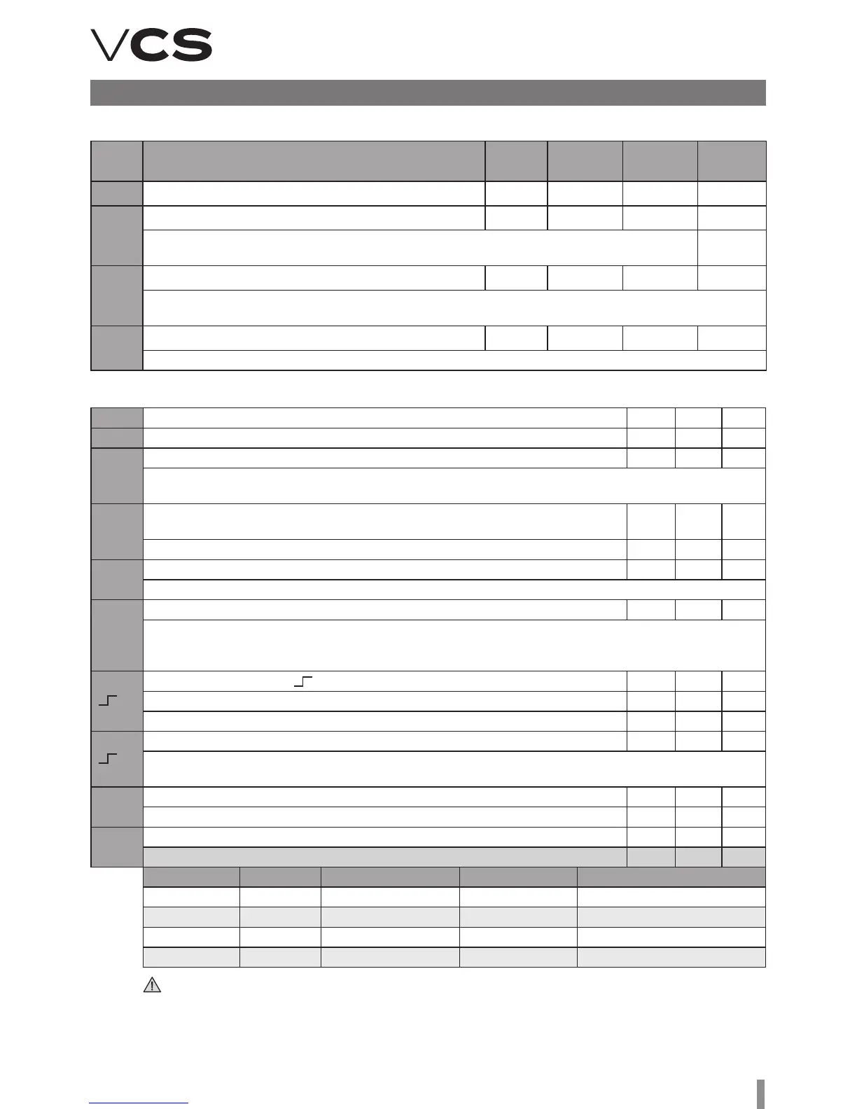
Code Parameter description and options Min. Max.
Factory
settings
Actual
settings
H5
Password 1 199 12
u0
Coolant: 0 7 1
0 = R22 1 = R134a 2 = R507 3 = R404A 4 = R407C 5 = R410A 6 = R124
7 = R744 (subcritical conditions)
uP
e used sensor type: 0 1 0
0 = PT4-07M (for R22/R134a/R507/R404A/R407C/R124) 1 = PT4-18M (for R410A)
2 = PT4-30M (for R744, subcritical)
ut
e used valve type: 1 5 5
1 = EX4 2 = EX5 3 = EX6 4 = EX7 5 = EX8
uu
Initial opening of the valve (%) 10 100 50
u9
Valve opening time (seconds) 1 30 5
uL
Low overheating reporting 0 2 1
0 = N/A (for flooded evaporator) 1 = Yes with auto-reset 2 = No with manual reset
switches at 0.5K (if it lasts 1 min); switches immediately at 3K
u5
Rated overheating (K)
If uL used (auto run) 3 30 6
If uL not used 0.5 30 6
u2
MOP function 0 1 1
0 = Yes 1 = No
u3
MOP settings (°C), saturated temperature * * X
Set by the manufacturer according to the used coolant.
+13°C for R22 +15°C for R134a +7°C for R507 +7°C for R404A +15°C for R407C+15°C for R410A
+50°C for R124
5
Used units (only for u3, u5, 1 0 1 0
0 = °C, K, bar 1 = °F, R, psig
(Psig is divided by 10 - example: displayed 12.5 equals 125 psig)
1
Displayed value 0 4 0
0 = measured overheating 1 = measured evaporating pressure, (bar); 2 = valve opening (%),
3 = measured water output temperature 4 = calculated evaporation temperature (°C) from measured pressure
u4
Overheating control method 0 1 0
0 = normal, 1 = slow
b1
Action of the battery if it fails. 0
(only for EC3-X33), according to the table:
*) Maximum and minimum values are dependent on the coolant type
Number Display Failure relay Valve Reset option aer replacement
0 – – controls –
1 Ab – controls –
2 Ab switches fully closed automatically
3 Ab (flashes) switches fully closed manually
If b1 is set to 0 or 1, the user must ensure suitable protection to protect the system against failures
caused by power supply breakdowns.