18
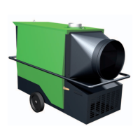
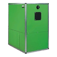
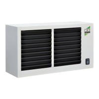
REMKO GPS series
Condensate water
With long pipes condensate can form, because
the temperature of the flue gas drops below
the condensation temperature. This must be
prevented through the following measures:
■
Through heat insulation of the flue gas pipes
■
Through the use of condensate water traps, where
the collected condensate is drained from the flue
gas pipe.
Note:
Appropriate condensate traps are available as
accessories.
They can be used with both horizontal and vertical
pipework.
Guide to selection
If the flue gas end piece is not connected directly
to the unit, but rather longer flue gas sections must
be overcome, ensure - according to the tot. length
and geometry of the flue gas routing - that the end
and extension pieces, as well as the elbows, exhibit
the correct diameter.
After fastening the flue gas routing, the pressure loss
for the respective unit must be determined.
The pressure loss is different with each unit, because
the flue gas flow rate depends on the output.
Add up the determined pressure losses
of the individual flue gas components and make sure
that the sum total does not exceed the value available
for the unit type to be used.
Note:
With the internal installation of coaxial tubes,
a maximum tube length of 3 m is permitted.
The end piece of the flue gas pipe must be installed
in accordance with the relevant national guidelines.
If there is a combustion air supply duct, the pressure
losses must be added to those of the flue gas pipe.
If the sum total of the pressure losses lies above
the available unit pressure, flue gas and fresh air pipes
with a larger diameter must be used. The calculation
must be performed once more for this.
The maximum possible duct lengths between the unit
and end piece are shown in the table.
When using flue gas elbows, it is necessary to take
the respective pressure losses into consideration.
Examples of pressure losses:
A 90° elbow with Ø 80
equates to 1.8 m straight pipe length
A 45° elbow with Ø 80
equates to 0.8 m straight pipe length
A 90° elbow with Ø 100
equates to 2.3 m straight pipe length
A 45° elbow with Ø 100
equates to 1.0 m straight pipe length
Examples for the design of flue gas pipe and
combustion air ductwork are represented on
the following pages.
Individually, the units are classified for
the installation versions
B23/C13/C33/C43/C53/C63
NOTE
Exceeding the permissible pressure losses
in the pipework reduces the heat output and safe
operation of the unit.
CAUTION
Installation work may only be carried out by
authorised qualified technicians.
 Loading...