22
REMKO GPS series
Electrical wiring
The electrical connection of the unit may only be carried
out by authorised technicians (electrical power company-
approved) in accordance with the applicable regulations.
A main/emergency shut-off switch should be installed in
an easily accessible position on the visible side of the unit
and protected against unintended actuation. The switch
must disconnect all poles of the unit with a minimum
contact opening of 3 mm from the power supply.
The units must be connected to the power supply
protected against polarity reversal.
Power supply 230V/50Hz,
Minimum cross-section of the power supply 1.5 mm².
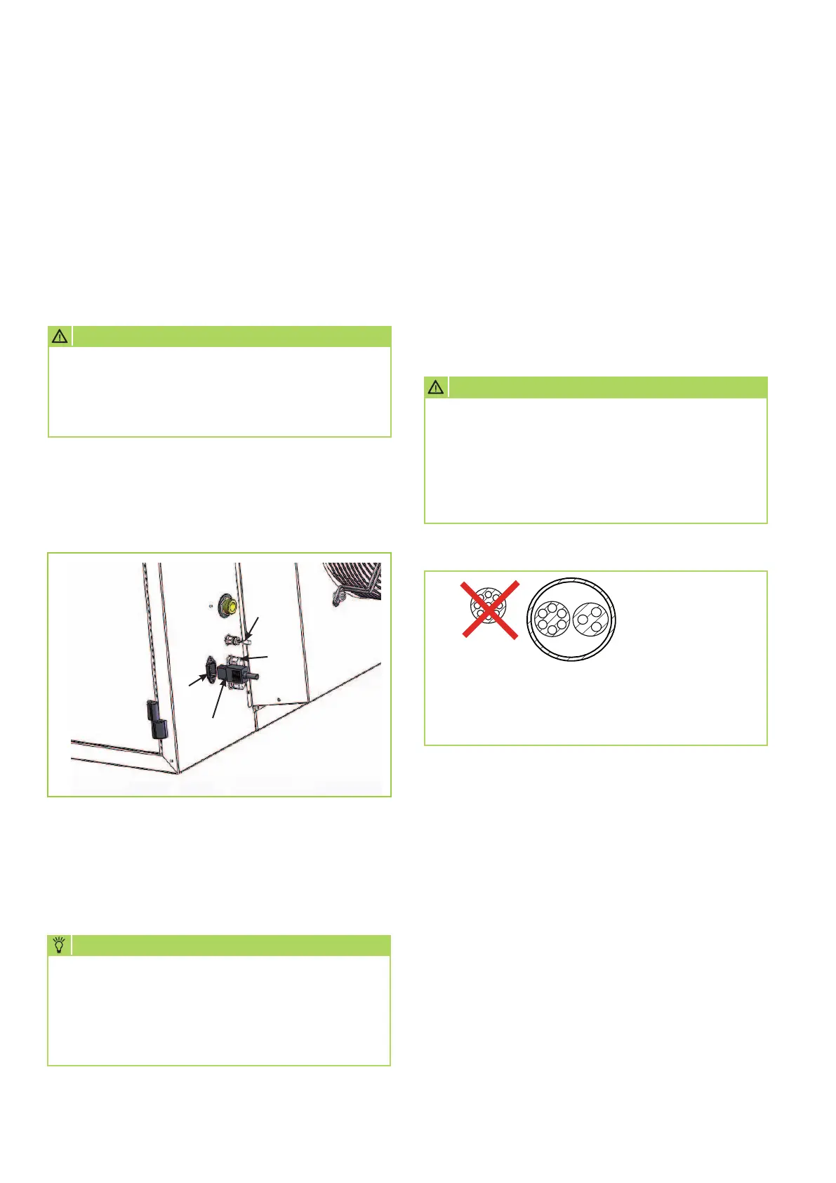
Rear panel legend:
= Unit power outlet
= Unit plug
= Cable guides
= Unit temperature probe
We reserve the right to modify the dimensions and design as part of the ongoing technical development process.
CAUTION
A multi-polar isolator with appropriate electrical
protection must be connected upstream to
the units.
The wire cross-section must be at least 1.5 mm².
NOTE
Phase and neutral lines must not be interchanged
during connection, because the flame monitoring
device will otherwise interrupt unit operation for
safety reasons.
Alarm F1 is displayed.
CAUTION
The main/emergency shut-off switch may only
be used in emergency situations or with extended
periods of non-use.
If it is switched off during the operation of
the unit, the electrical supply-air fan cannot
cool the combustion chamber. This can result
in damage to the unit.
Connection of room thermostat and remote control
The hot air heaters from the GPS series must always
be connected to a thermostat, a timer or a room
temperature controller, so that the user can switch
the unit on and off. The operator or installer is
required to install the unit circuitry in the room.
If multiple switches serve to switch off the burner,
these must be connected in series.
NO!
YES
S
R = Controller cable
S = Live cable
R
 Loading...