26
REMKO GPS series
Gas connection
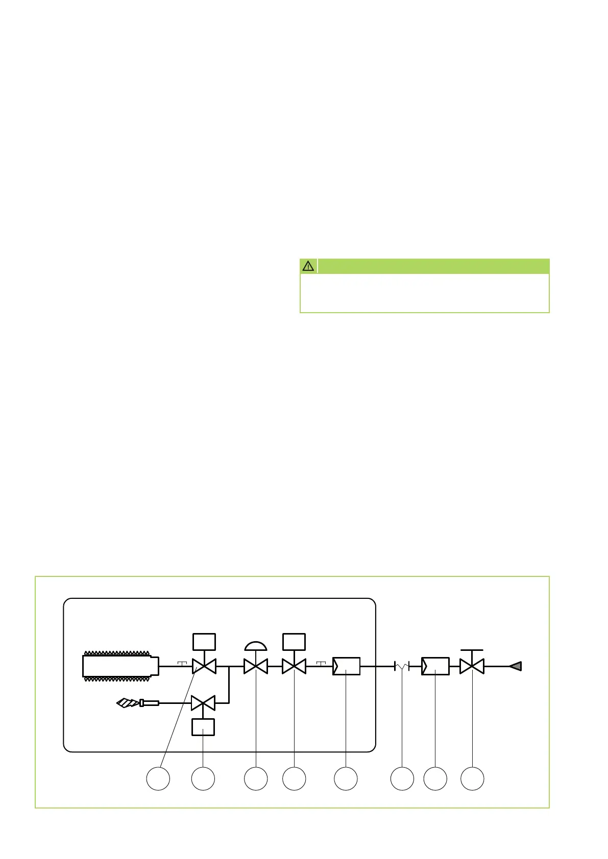
LEGEND
1 = Electrical gas solenoid valve main burner
2 = Electrical gas solenoid valve ignition burner
3 = Pressure regulator
4 = Electrical gas safety valve
5 = Gas filter (small filter area)
6 = Vibration-inhibiting connection piece (provided
by the customer)
7 = Gas filter with large filter area (provided
by the customer)
8 = Gas stopcock (provided by the customer)
1 2 3 4 5 6 7 8
Schematic layout of the factory-supplied gas components
to be executed on-site
by the installation company
The installation of the gas connection may only
be executed by authorised technicians (authorised
by the municipal gas supplier) in observance of
the applicable provisions for the respective gas type.
The cross-section of the ductwork should be
determined according to the connection value
of the unit, the total output resistance as well
as the amount of gas supply pressure.
The necessary gas supply pressure (depending on gas
type) should be ensured by the customer.
The necessary amount of gas and the necessary
gas pressure must be continuously available during
operation of the unit according to its output.
The unit connection takes place through an R 3/4“
external thread connection.
The gas supply should be executed with a suitable,
removable screw connection free of voltage and
vibration.
The components described in the applicable gas
guidelines as well as the locally required components
in the gas supply, such as gas pressure regulators,
isolation devices, etc., are not included in the scope of
delivery and must be provided by the customer.
Installing a high-output compatible gas filter without
pressure regulator is also recommended, because
the filter area of the serial filter installed above the gas
valve is limited.
The applicable standards allow a maximum pressure
of 60 mbar in the heating room; higher pressure
values must be reduced prior to entrance to
the heating or installation room of the unit.
Prior to the initial commissioning, the gas supply
line must be thoroughly cleaned and bled through
appropriate measures.
It must be ensured that the connection of the unit to
the gas supply line is executed gas-tight.
All screw connections of the unit and the gas supply
must be inspected for leakage integrity.
If leak detection sprays are used, these must
correspond to DIN 30657 (corrosion-free).
We reserve the right to modify the dimensions and design as part of the ongoing technical development process.
CAUTION
Installation work on the gas system and
the supply lines may only be conducted
by licensed technicians.
 Loading...