2010 Release
E-25
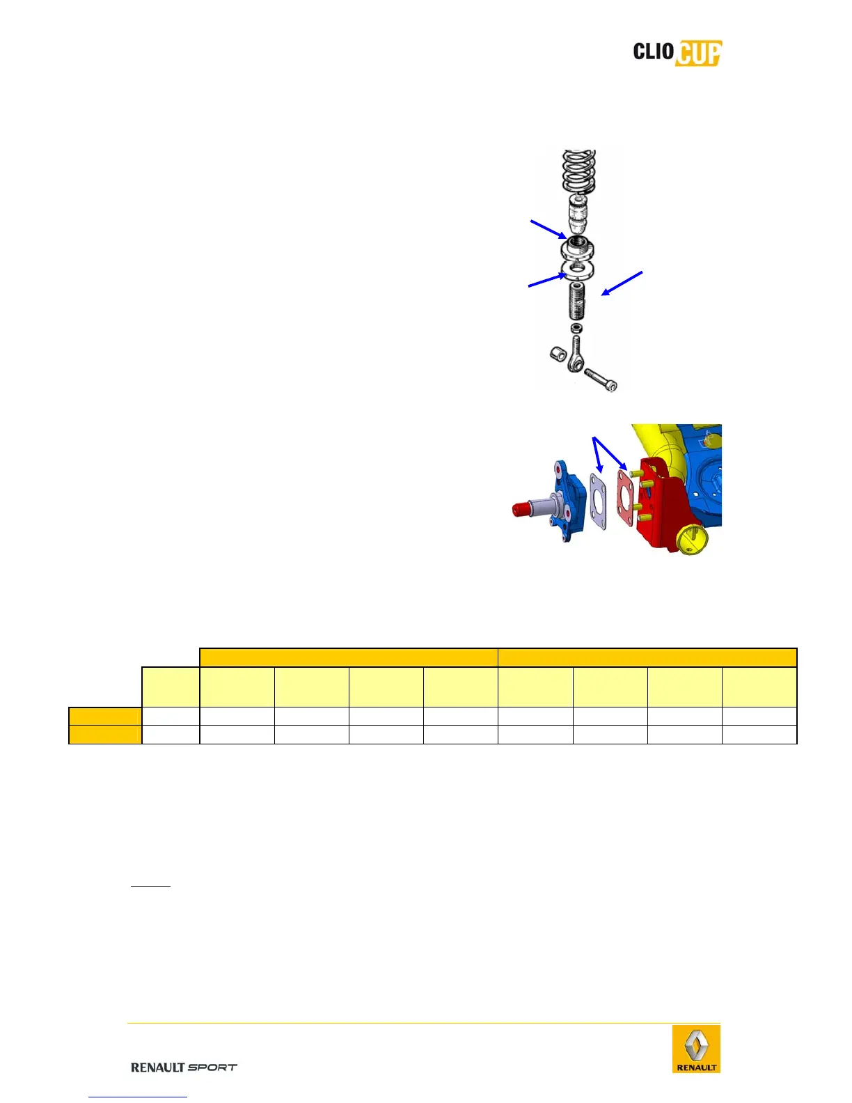
4.3.3 ADJUSTMENT OF GEOMETRY
Body height
Body height is adjusted using the nut (1)
mounted on the extension (2).
Loosen the locknut (3).
Adjust body height by tightening or
loosening the nut.
Once the required height has been reached,
tighten the locknut.
Alignment and camber
The alignment and camber of the rear axle are
adjusted by inserting shims (1) between the
hub carrier and the axle.
Depending on the required effect, the shims
should be positioned according to the thickest
edge.
The correspondence between the shims and their resulting alignment/camber is given
in the following table.
Camber shim Alignment shim
No
shim
10'
77 11 160
176
20'
77 11 160
175
30'
77 11 160
174
1°
77 11 160
173
10'
77 11 160
172
20'
77 11 160
171
30'
77 11 160
170
1°
77 11 160
169
Camber -1,23
-0,1 -0,19 -0,29 -0,98 -0,03 -0,05 -0,08 -0,17
Alignment 0,21
0,03 0,05 0,09 0,16 -0,1 -0,19 -0,28 -0,84
To obtain the recommended setup (see 4-1 Setup) the following shim set should be
used:
Alignment (wheel opening): one 1° shim,
Camber (wheel negative camber): one 1° shim.
Note:
To achieve the same setting for both rear axle wheels, the shims used on
the left and right-hand sides may differ.
3
1
1
2