RL78/G13 CHAPTER 12 SERIAL ARRAY UNIT
R01UH0146EJ0100 Rev.1.00 552
Sep 22, 2011
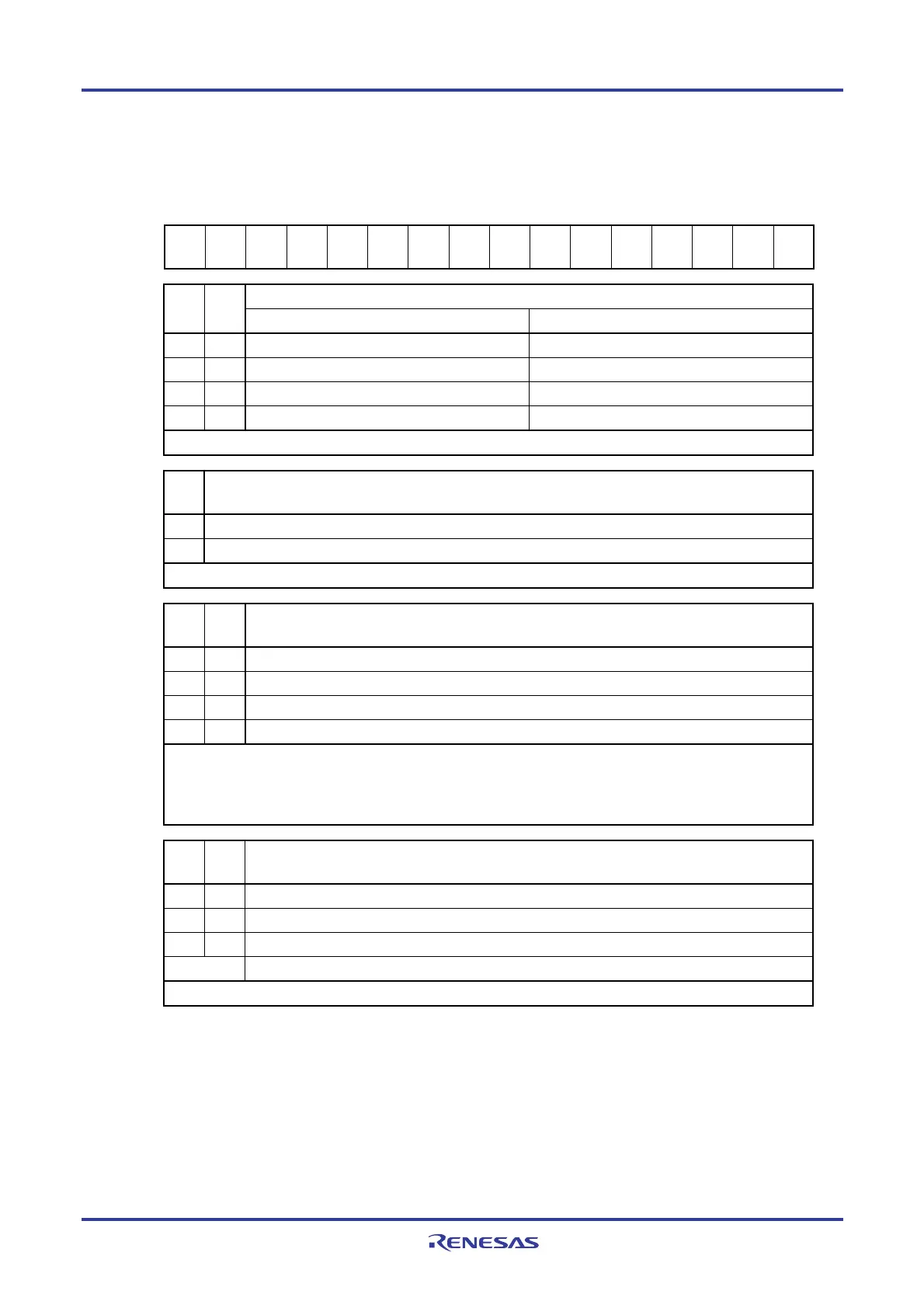
Figure 12-8. Format of Serial Communication Operation Setting Register mn (SCRmn) (2/2)
Address: F0118H, F0119H (SCR00) to F011EH, F011FH (SCR03), After reset: 0087H R/W
F0158H, F0159H (SCR10) to F015EH, F015FH (SCR13)
Symbol 15 14 13 12 11 10 9 8 7 6 5 4 3 2 1 0
SCRmn
TXE
mn
RXE
mn
DAP
mn
CKP
mn
0
EOC
mn
PTC
mn1
PTC
mn0
DIR
mn
0
SLCm
n1
Note 1
SLC
mn0
0 1
DLSm
n1
Note 2
DLS
mn0
Setting of parity bit in UART mode
PTC
mn1
PTC
mn0
Transmission Reception
0 0 Does not output the parity bit. Receives without parity
0 1 Outputs 0 parity
Note 3
. No parity judgment
1 0 Outputs even parity. Judged as even parity.
1 1 Outputs odd parity. Judges as odd parity.
Be sure to set PTCmn1, PTCmn0 = 0, 0 in the CSI mode and simplified I
2
C mode.
DIR
mn
Selection of data transfer sequence in CSI and UART modes
0 Inputs/outputs data with MSB first.
1 Inputs/outputs data with LSB first.
Be sure to clear DIRmn = 0 in the simplified I
2
C mode.
SLCm
n1
Note 1
SLC
mn0
Setting of stop bit in UART mode
0 0 No stop bit
0 1 Stop bit length = 1 bit
1 0 Stop bit length = 2 bits (mn = 00, 02, 10, 12 only)
1 1 Setting prohibited
When the transfer end interrupt is selected, the interrupt is generated when all stop bits have been completely
transferred.
Set 1 bit (SLCmn1, SLCmn0 = 0, 1) during UART reception and in the simplified I
2
C mode.
Set no stop bit (SLCmn1, SLCmn0 = 0, 0) in the CSI mode.
DLSm
n1
Note 2
DLS
mn0
Setting of data length in CSI and UART modes
0 1 9-bit data length (stored in bits 0 to 8 of the SDRmn register) (settable in UART mode only)
1 0 7-bit data length (stored in bits 0 to 6 of the SDRmn register)
1 1 8-bit data length (stored in bits 0 to 7 of the SDRmn register)
Other than above
Setting prohibited
Be sure to set DLSmn1, DLSmn0 = 1, 1 in the simplified I
2
C mode.
Notes 1. The SCR00, SCR02, SCR10, and SCR12 registers only.
2. The SCR00 and SCR01 registers and SCR10 and SCR11 registers for 80, 100 and 128-pins products
only. Others are fixed to 1.
3. 0 is always added regardless of the data contents.
Caution Be sure to clear bits 3, 6, and 11 to “0”. (Also clear bit 5 of the SCR01, SCR03, SCR11, or SCR13
register to 0, as well as bit 1 of the SCR02, SCR03, SCR12, SCR13 registers, and SCR10, or
SCR11 registers for 20 to 64-pin products.). Be sure to set bit 2 to “1”.
Remark m: Unit number (m = 0, 1), n: Channel number (n = 0 to 3), p: CSI number (p = 00, 01, 10, 11, 20, 21, 30, 31)
<R>
<R>

 Loading...


