RZ Family / RZ/G, RZ/A Series 2. Functional Specifications
R01UH0990EJ0101 Rev.1.01 Page 48 of 83
Jul 28, 2022
2.5 ADC Interface
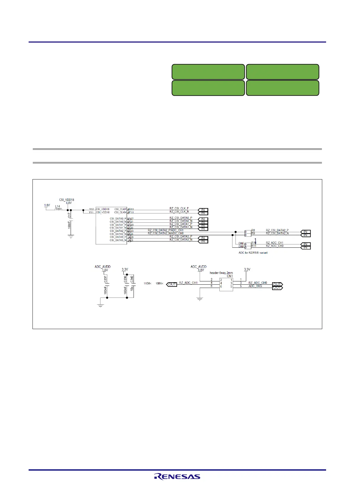
Figure 2.6 shows a block diagram of the ADC interface.
When the RZ/Five is used, the pin location is different from the RZ/G2UL, so option resistors are required.
The 6-pin connector is implemented on this board and 2ch input channels can be used as the analog signal.
NOTE
ADC_TRG is only available when SD0 is used for eMMC memory (not when microSD card is used).
Figure 2.6 Block Diagram of ADC I/F

 Loading...


