RZ Family / RZ/G, RZ/A Series 2. Functional Specifications
R01UH0990EJ0101 Rev.1.01 Page 51 of 83
Jul 28, 2022
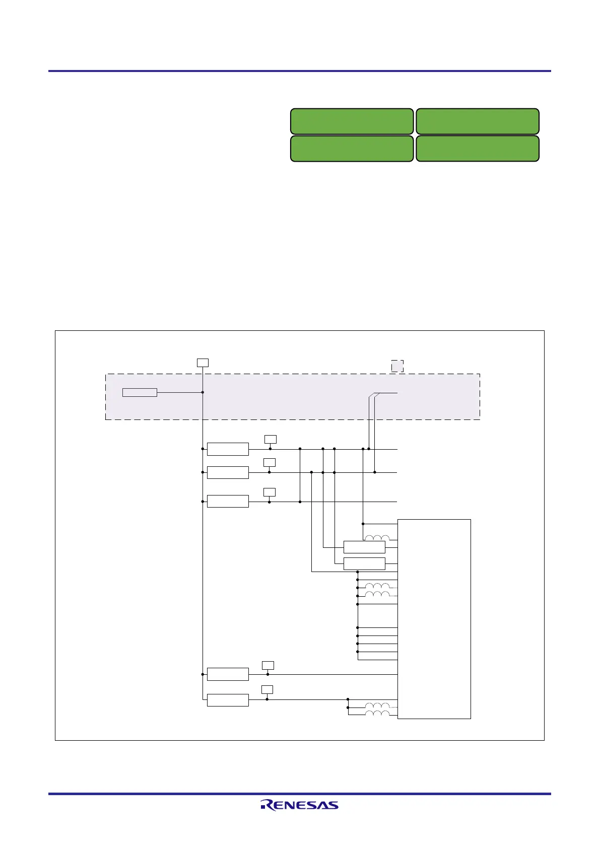
2.8 Power Supply Configuration
Figure 2.9 shows a block diagram of power configuration for the RTK9743U11S01000BE (Evaluation board Kit for
RZ/G2UL MPU).
This board has one USB Type-C receptacle for power input with USB Power Delivery. The input voltage of VBUS can
be selected between 5V and 9V.
The default setting for controlling the input voltage level is 5V (max 3A input) with SW11-4 is turned on. When the
switch is turned off, the input voltage is 9V (max 3A input). Only when the RTK9743U11S01000BE is connected to
external devices that requires a lot of power and is expected to run out of power, the SW 11-4 is turned off.
The 5V power supply is supplied to the PMIC installed on the RTK9743U11C01000BE, and the PMIC generates the
power supply voltage for each interface.
VBUS
DDR_VDDQ[0:5]
PVDD[0:6]
USB_VDD33[0:1]
PVDD182533_1
ADC_AVDD18
SPI_PVDD
USB_VDD18[0:2]
VDD18
CSI_VDD18[0:1]
PVDD182533_0
VDD18
OTP_VDD18
PLL[1:6]_AVDD18
SD0_PVDD
SD1_PVDD
PLL23_DVDD11
VDD[0:24]
PLL5_DVDD11
RZ/G2UL
5.0V 1.8V 1.8V peripheral device
5.0V
5.0V 1.1V
5.0V 3.3V 3.3V peripheral device
1.1V
5.0V 1.2V
VDDQ_DDR
USB Type-C (CN6)
Ethernet PHY
5.0V 1.2V
ETH_VDD
3.3V/1.8V
3.3V/1.8V
1.8V
3.3V
To SUB board
Note: shows the Carrier Board
 Loading...


