XCell® ATF 2 and 4 Stainless Steel Housings
SG-SSATF24 rev 1
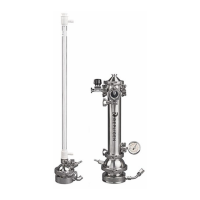
Figure 3. Orientation of silicone diaphragm in XCell® ATF 2 Stainless Steel Housing
6.2 XCell® ATF 2 Device Diaphragm Placement
Important: The silicone diaphragm must be replaced after each run, prior to sterilization.
1. Set the pump air-side (PA) hemisphere (Figure 3
, 2) on a flat surface with the open (concave)
side of the hemisphere facing up.
2. P
lace diaphragm (3) with the convex side oriented up onto the PA hemisphere, and place
the PL hemisphere, wide opening down, on top of the diaphragm.
3. Assure the diaphragm gasket O-ring is positioned uniformly around the periphery of the
pump O-ring groove. Place the pump liquid-side (PL) hemisphere (1) on top. The two
hemispheres, with diaphragm in between, should be equally spaced.
4. Clamp (4) the two hemispheres together.
5. Secure the diaphragm pump to the stand.
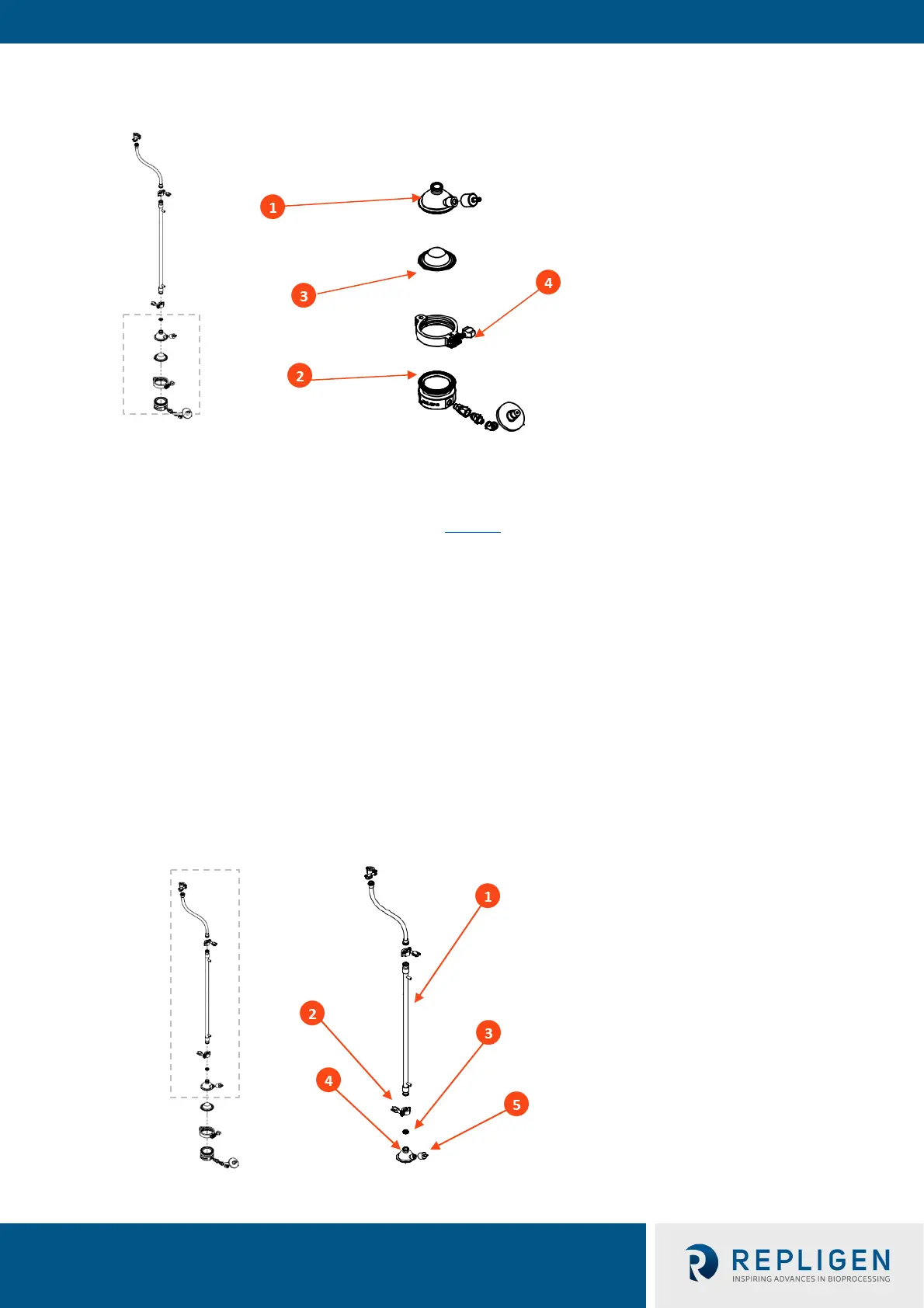
6.2.1 XCell® ATF 2 Stainless Steel Housing hollow fiber filter installation
XCell® ATF 2 Stainless Steel Housing accommodates a variety of hollow fiber modules. For selection
support, please contact your local Repligen Field Applications Specialist (FAS).
Figure 4. XCell® ATF 2 Stainless Steel Housing Installation of HFM
1. Pump liquid-side hemisphere
2. Pump air-side hemisphere
3. Diaphragm
4. Clamp
1. Hollow fiber module (not included)
2. Clamp
3. Gasket
4. PL hemisphere
5. Drain port