XCell® ATF 2 and 4 Stainless Steel Housings
SG-SSATF24 rev 1
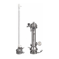
7.3.2 Tubing set kit for XCell® ATF 4 Stainless Steel Housing connected to glass bioreactor
Assembly of the housing, tubing set, and accessories is completed prior to autoclaving.
Figure 9. XCell® ATF 4 Stainless Steel Housing connection to glass bioreactor (tri-clamp)
A. TC:DIP-10/250 or TC:DIP-10/450 (dip tube)
B. ATF4-A2B-TC (A2B)
C. SSATF-PSK-V2 (pressure sensor)
D. SSATF4-TSK
D1. Top permeate
D2. Drain
Connection instructions (Figure 9):
1. Ensure dip tube (A) is attached to head plate of bioreactor.
2. Attach A2B tubing (B) to XCell® ATF 4 and bioreactor head plate.
3. Connect pressure sensor (C) to XCell® ATF 4.
4. Attach top permeate (D1) to pressure sensor (C).
5. Attach drain (D2) to hose barb. Autoclave.
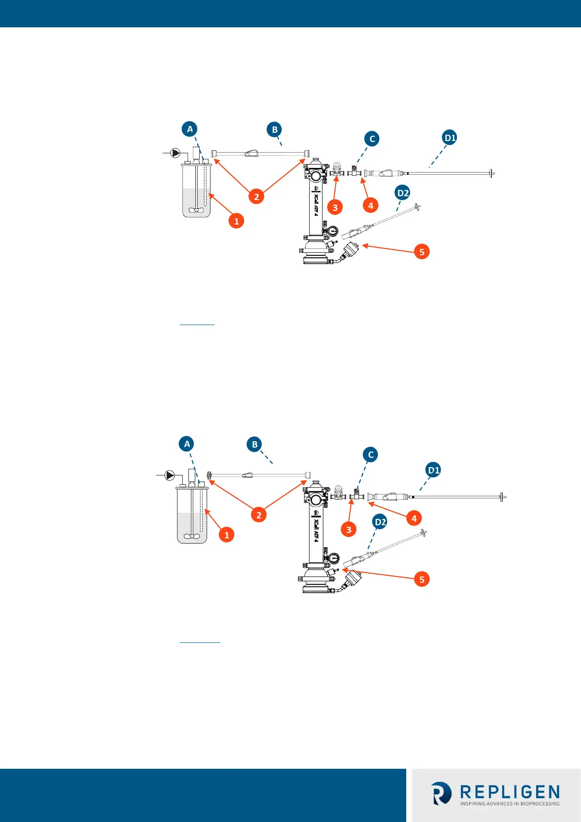
Figure 10. XCell® ATF 4 Stainless Steel Housing connection to glass bioreactor (AseptiQuik®)
A. TC:DIP-10/250 or TC:DIP-10/450 (dip tube)
B. ATF4-A2B-TCAQ (A2B)
C. SSATF-PSK-V2 (pressure sensor)
D. SSATF4-TSK
D1. Top permeate
D2. Drain
Connection instructions (Figure 10):
1. Ensure dip tube (A) is attached to head plate of bioreactor.
2. Attach A2B tubing (B) to XCell® ATF 4 and bioreactor head plate.
Note: Bioreactor adapter tubing not provided.
3. Connect pressure sensor (C) to XCell® ATF 4.
4. Attach top permeate (D1) to pressure sensor (C).
5. Attach drain (D2) to hose barb. Autoclave.
7.4 Disassembly and maintenance