KrosFlo® TFDF™ Lab System
XCell® ATF 2 and 4 Stainless Steel Housings
SG-SSATF24 rev 1
List of tables
Table 1. Explanation of user attention phrases ...................................................................................... 8
Table 2. Explanation of symbols ............................................................................................................. 8
Table 3. Dimensions ................................................................................................................................ 9
Table 4. Suggested scale of operation .................................................................................................... 9
Table 5. Headplate fitting part numbers ............................................................................................... 13
Table 6. XCell® ATF 2 tubing set kit options .......................................................................................... 13
Table 7. XCell® ATF 2 required accessories ........................................................................................... 13
Table 8. Headplate fitting part numbers ............................................................................................... 19
Table 9. XCell® ATF 4 tubing set kit options .......................................................................................... 19
Table 10. XCell® ATF 4 required accessories ......................................................................................... 19
Table 11. XCell® ATF 2 spare parts ........................................................................................................ 23
Table 12. XCell® ATF 4 spare parts ........................................................................................................ 24
List of figures
Figure 1. Pressure and exhaust strokes .................................................................................................. 8
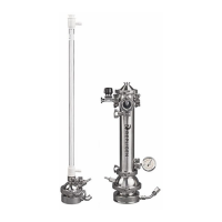
Figure 2. XCell® ATF 2 Stainless Steel Housing ...................................................................................... 10
Figure 3. Orientation of silicone diaphragm in XCell® ATF 2 Stainless Steel Housing .......................... 11
Figure 4. XCell® ATF 2 Stainless Steel Housing Installation of HFM ...................................................... 11
Figure 5. XCell® ATF 2 Stainless Steel Housing connection to glass bioreactor (tri-clamp) .................. 14
Figure 6. XCell® ATF 2 Stainless Steel Housing connection to glass bioreactor
(AseptiQuik®/ReadyMate™) ......................................................................................................... 14
Figure 7. XCell® ATF 4 Stainless Steel Housing ...................................................................................... 16
Figure 8. Orientation of silicone diaphragm in XCell® ATF 4 Stainless Steel Housing .......................... 17
Figure 9. XCell® ATF 4 Stainless Steel Housing connection to glass bioreactor (tri-clamp) .................. 20
Figure 10. XCell® ATF 4 Stainless Steel Housing connection to glass bioreactor (AseptiQuik®) ........... 20