Slide the rotor up to the stop onto the motor shaft, which is prevented from rotating by the
engine brake.
NOTICE If it is hard to slide the rotor or if it cannot be pushed up to the stop, check the correct
and firm fit of the feather key (PF) on the motor shaft (MW). In addition, the motor shaft can be
oiled with some machine oil.
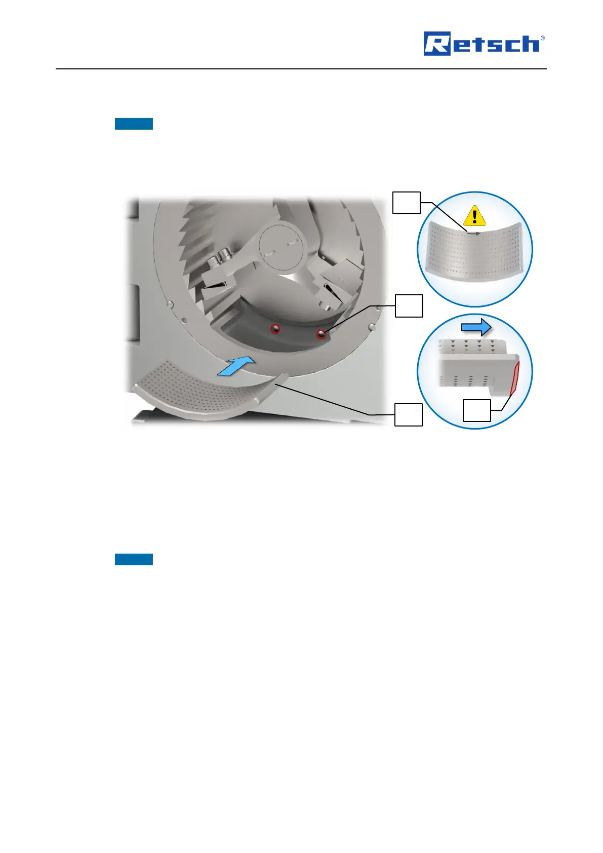
6.6.3 Inserting the Bottom Sieve
The bottom sieve (BS) has a direction arrow (BS1), which indicates the direction of rotation of
the rotor (counterclockwise). Furthermore, the bottom sieve is provided with a phase (PH) on
one side so that only this side fits over the two cylinder pins (ZS) in the grinding chamber.
Align the bottom sieve so, that the direction arrow (BS1) corresponds with the direction of
rotation of the rotor and the side with the phase is facing towards the grinding chamber.
Slide the bottom sieve (BS) into the grinding insert (ME) up to the stop.
NOTICE If the door of the SK 300 cannot be closed, check the correct alignment of the bottom
sieve, and make sure that the bottom sieve has been completely pushed in.
6.7 Removing the Grinding Set
The removal of the grinding set is preferably carried out in the following sequence:
1. Bottom sieve
2. Rotor
3. Grinding insert
6.8 Mounting the Sample Receptacle
By the use of the textile filter hose (L), or a ring filter that is available as an optional accessory,
attached between the discharge flange (AF) and the collecting receptacle (M), the airflow
generated by the rotating rotor can be dissipated and the material throughput can be
accelerated.