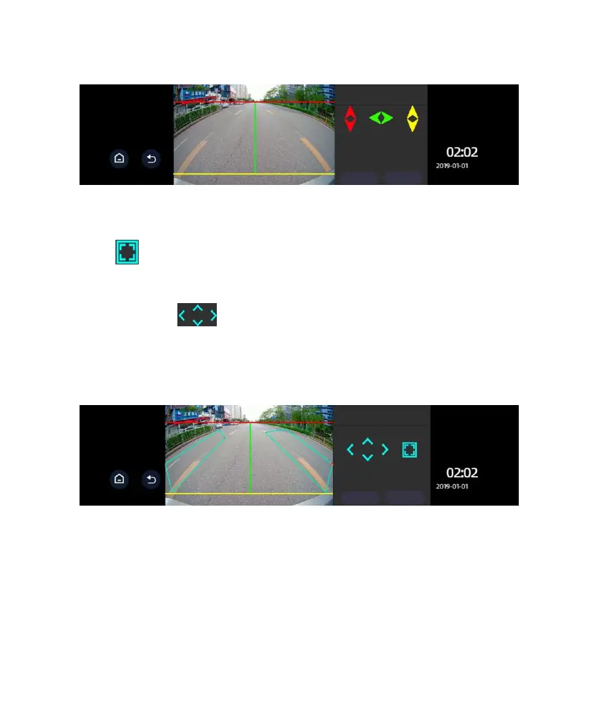
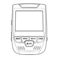
6. Warning Range Setup:
Click to switch among the four corners of both the left and right square
zones. The corner indicated by the red spot means the zone is currently
adjustable. Click to adjust the warning range. By touching one of the
four arrows you may move it up, down, left, or right. Click Save after making
the appropriate adjustments. Only in this way can the calibration data be saved.
7. Testing: When testing is on, as shown above, the image from the rearview
camera shows two warning zones marked in cyan. It is not shown when the
button is off. This function is mainly used for demonstration of the warning
ranges. To avoid interference with the image display, it is off as a default after
starting the device each time. It is to be manually turned on if such a display is
desired.
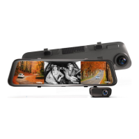
Move the red line to the interface
between the sky and ground. Move
the green line to the focal point where
the road intersects with the horizon.
Move the yellow line to the interface
between car’s tail and the ground.