RE 91 401/09.00 | A2FO Mobile Hydraulics | Bosch Rexroth AG 19/20
Installation and Commissioning Guidelines
General
At start-up and during operation the pump housing has imperatively
to be filled up with hydraulic fluid (filling of the case chamber). Start-
up has to be carried out at low speed and without load till the system
is completely bleeded.
At a longer standstill the case may discharge via operating line. At
new start-up a sufficient filling of the housing has to be granted.
The leakage oil in the housing has to be discharged to the tank via
highest positioned case drain port. The min. suction pressure at port
S should not fall below 0,8 bar absolute.
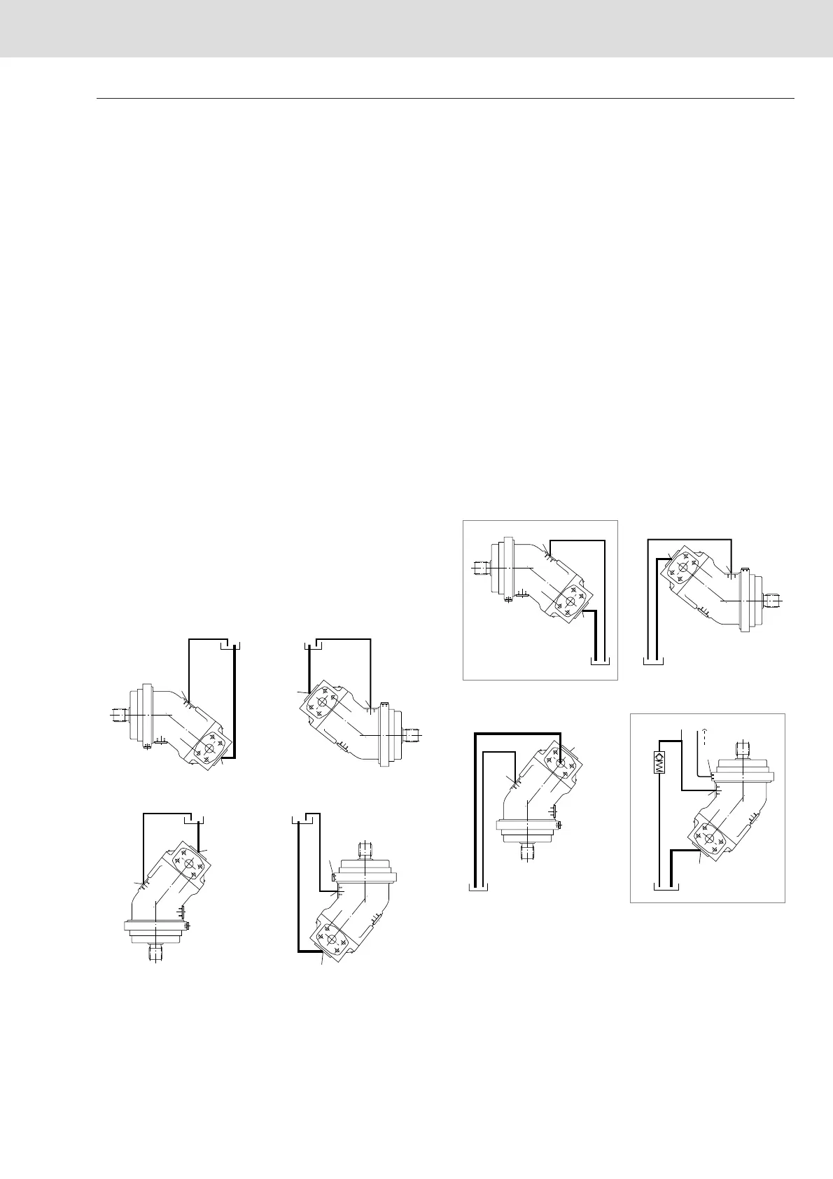
Installation position
Optional
Installation below tank level
Pumps below min. oil level in the tank (standard)
➔ Fill up axial piston pump before start-up via highest positioned
case drain port (note for the “shaft on top” installation position:
fill until oil starts escaping from air bleed port R or U).
➔ Recommendation: Fill up suction lines
➔ Operate pump at low speed (igniton speed) till pump system is
completely filled up
➔ Minimum immersion depth of the suction line or drain line in
the tank:
200 mm (relative to the min. oil level in the tank).
Installation on top of tank level
Pump on top of min. oil level in the tank
➔ Actions as installation below tank level
➔ Installation position 1 and 2:
If the pump is left at standstill for a long period, the oil in the
housing chamber may fully drain out through the operating
lines (air entering via the shaft seal). Consequently, on
restarting, the bearings will be insufficiently lubricated. You
should therefore refill the axial piston unit via the highest
positioned drain port before restarting (Installation position 2:
air bleed via port R or U).
➔ Installation position 2 (shaft on top)
In this installation position, the bearings will be insufficiently
lubricated even if the housing chamber is only partially drained.
To prevent oil draining via the drain port, insert a check valve in
the drain line (opening pressure 0.5 bar).
➔ Note: min. admissible presssure at port S (min. suction pressure)
T
2
T
2
R (U)
T
1
T
1
S
S
S
S
T
2
T
2
R(U)
T
1
T
1
S
S
S
S
0,5 bar
*
2
1
*
 Loading...