6/20 Bosch Rexroth AG | Mobile Hydraulics A2FO | RE 91 401/09.00
Code explanation
a = distance of F
q
from shaft shoulder
F
q max
= max. perm. radial force at distance a
(at intermittent operation)
±F
ax max
= max. perm. axial force when stationary
or when axial piston unit is running at zero pressure
±F
ax perm.
/bar= perm. axial force/bar working pressure
The direction of the max. perm. axial force must be noted by
sizes 5...200:
- F
ax
= increases bearing life
+ F
ax
= reduces bearing life
(avoid if possible)
Output drive
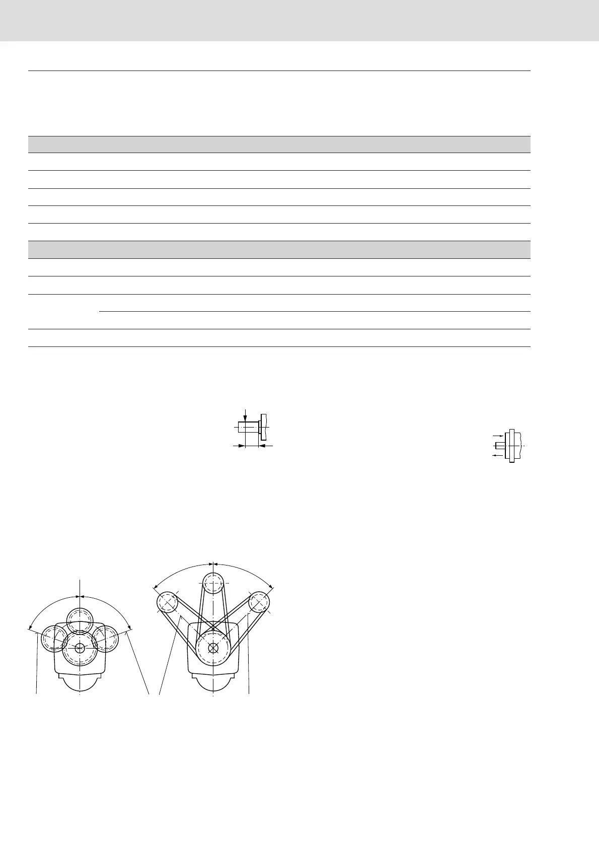
Permissible axial and radial loads on drive shaft
The values given are maximum values and do not apply to continuous operation
Size 5 10 12 16 23 28 32 45 56 63 80
a
mm
12 16 16 16 16 16 16 18 18 18 20
F
q max
N
710 2350 2750 3700 4300 5400 6100 8150 9200 10300 11500
±F
ax max
N
180 320 320 320 500 500 500 630 800 800 1000
±F
ax perm.
/bar
N/bar
1,5 3,0 3,0 3,0 5,2 5,2 5,2 7,0 8,7 8,7 10,6
Size 90 107 125 160 180 200 250 355 500 710 1000
a
mm
20 20 20 25 25 25 41 52,5 52,5 67,5 67,5
F
q max
N
12900 13600 15900 18400 20600 22900 1200
1
) 1500
1
) 1900
1
) 3000
1
) 2600
1
)
±F
ax max
N
+F
ax max
1000 1250 1250 1600 1600 1600 4000 5000 6250 10000 10000
- F
ax max
1000 1250 1250 1600 1600 1600 1200 1500 1900 3000 2600
±F
ax perm.
/bar
N/bar
10,6 12,9 12,9 16,7 16,7 16,7
2
)
2
)
2
)
2
)
2
)
1
) Axial piston unit in stationary or in bypass operation, please contact us when appearing higher forces!
2
) Please contact us!
Technical Data
Optimal force direction of F
q
(valid for sizes 10...180)
By means of appropriate force directions of F
q
the bearing load caused
by inside rotary group forces can be reduced. An optimal life
expectation of the bearing can be reached.
F
q
a
-
+
F
ax
A B
A B
ϕ
o
p
t
=
4
5
°
ϕ
o
p
t
=
4
5
°
ϕ
o
p
t
=
7
0
°
ϕ
o
p
t
=
7
0
°
clockwise rotation
pressure at port B
clockwise rotation
pressure at port B
anti-clockwise rotation
pressure at port A