RE 91 401/09.00 | A2FO Mobile Hydraulics | Bosch Rexroth AG 5/20
2,0
1,8
1,6
1,4
1,2
1,0
0,8
0
1
2
3
4
speed n/n
max
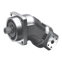
Note:
- max. perm. speed n
max perm.
(speed limit)
- min. perm. pressure at port S
- admissible values for the drive shaft seal
Maximum permissible speed with increased inlet pressure
p
abs
at suction port S
inlet pressure p
abs
in bar
Table of values (theoretical values, without considering η
mh
and η
v
; values rounded)
Size 5 10 12 16 23 28 32 45 56 63 80
Displacement
V
g
cm
3
4,93 10,3 12,0 16,0 22,9 28,1 32 45,6 56,1 63 80,4
Max. speed
1
)
n
max
rpm 5600 3150 3150 3150 2500 2500 2500 2240 2000 2000 1800
Max. perm. speed with increased
n
max perm.
rpm 8000 6000 6000 6000 4750 4750 4750 4250 3750 3750 3350
input pressure p
abs
Max. perm. output flow, at n
max
2
)
q
V max
L/min 27 32 37 49 56 68 78 99 109 122 140
Max. power ∆p = 350 bar
P
max
kW 14,5
3
)19222933414760657484
at q
v max
∆p = 400 bar
P
max
kW – 22 25 34 38 47 53 68 75 84 96
Torque constants
T
K
Nm/bar 0,076 0,164 0,19 0,25 0,36 0,445 0,509 0,725 0,89 1,0 1,27
Perm. torque ∆p = 350 bar
T
Nm 24,7
3
) 57 67 88 126 156 178 254 312 350 445
∆p = 400 bar
T
Nm – 65 76 100 144 178 204 290 356 400 508
Case volume L 0,17 0,17 0,17 0,20 0,20 0,20 0,33 0,45 0,45 0,55
Moment of inertia
J
kgm
2
0,00008 0,0004 0,0004 0,0004 0,0012 0,0012 0,0012 0,0024 0,0042 0,0042 0,0072
about drive axis
Weight (approx.)
m
kg 2,5 5,4 5,4 5,4 9,5 9,5 9,5 13,5 18 18 23
Size 90 107 1 25 160 180 200 250 355 500 710 1000
Displacement
V
g
cm
3
90 106,7 125 160,4 180 200 250 355 500 710 1000
Max. speed
1
)
n
max
rpm 1800 1600 1600 1450 1450 1550 1500 1320 1200 1200 950
Max. perm. speed with increased
n
max perm.
rpm 3350 3000 3000 2650 2650 2750 1800 1600 1500 1500 1200
input pressure p
abs
Max. perm. output flow, at n
max
2
)
q
V max
L/min 158 167 196 228 255 304 364 455 582 826 922
Max. power ∆p = 350 bar
P
max
kW 95 100 117 135 152 181 219 273 350 497 554
at q
v max
∆p = 400 bar
P
max
kW 108 114 133 155 174 207 –––––
Torque constants
T
K
Nm/bar 1,43 1,70 1,99 2,55 2,86 3,18 3,99 5,65 7,96 11,3 15,9
Perm. torque ∆p = 350 bar
T
Nm 501 595 697 889 1001 1114 1393 1978 2785 3955 5570
∆p = 400 bar
T
Nm 572 680 796 1016 1144 1272 –––––
Case volume L 0,55 0,8 0,8 1,1 1,1 2,5 3,5 7,8
Moment of inertia
J
kgm
2
0,0072 0,0116 0,0116 0,0220 0,0220 0,0378 0,061 0,102 0,178 0,55 0,55
about drive axis
Weight (approx.)
m
kg 23 32 32 45 45 66 73 110 155 322 336
1
) The values shown are valid for an absolute pressure (p
abs
) of 1 bar at the suction inlet S and when operated on mineral oil.
By increase of the input pressure (p
abs
> 1 bar) the rotational speeds can be increased to the max. admissible speeds (speed limits) (see diagram).
2
) 3 % volumetric loss included
3
)
∆
p = 315 bar
Calculation of size
V
g
• n • η
v
Flow q
V
= in L/min
1000
V
g
• ∆p 1,59 • V
g
• ∆p
Torque T = = in Nm
20 π • η
mh
100 • η
mh
2 π • T • nT • nq
V
• ∆p
Power P = = = in kW
60 000 9549 600 • η
t
V
g
= geometric displacement per rev. in cm
3
T = torque in Nm
∆p = pressure differential in bar
n = speed in rpm
η
v
= volumetric efficiency
η
mh
= mech. -hyd. efficiency
η
t
= overall efficiency
sizes 5...200
sizes 250...1000
Technical Data