Do you have a question about the REXROTH A2FO Series and is the answer not in the manual?
Guidance on selecting the appropriate hydraulic fluid for A2FO pumps.
Recommended viscosity for optimal pump efficiency and service life.
Maximum and minimum permissible viscosity values for different pump sizes.
Factors to consider when selecting hydraulic fluid based on temperature.
Specifies required cleanliness levels for pressure fluid and its impact.
Permissible case drain pressure and its effect on shaft seal life.
Nominal and peak pressure limits for different pump sizes.
Details on long-life bearings for extended service life and HF-fluids.
Admissible temperature ranges for FKM and NBR shaft seal rings.
Information on bearing and housing flushing via port U for specific sizes.
Formulas for calculating flow, torque, and power based on pump parameters.
Permissible axial and radial loads on the drive shaft for various sizes.
Guidance on drive shaft force direction to reduce bearing load and improve life.
Detailed physical dimensions and connection port information for Size 5.
General guidelines for pump start-up, housing filling, and case drain port usage.
Procedure for pumps installed below the minimum oil level in the tank.
Procedure for pumps installed above the minimum oil level in the tank.
| Series | A2FO |
|---|---|
| Category | Water Pump |
| Fluid | Hydraulic Oil |
| Circuit Type | Open circuit |
| Rotation | Clockwise or counter-clockwise |
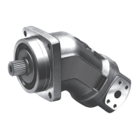
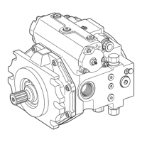
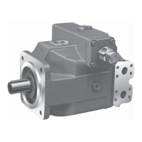
| Type | Axial Piston Pump |
| Weight | Dependent on size |
| Shaft Type | Splined |
| Port Connection | SAE Flange |
| Displacement Range | 5 to 1000 cm³/rev |