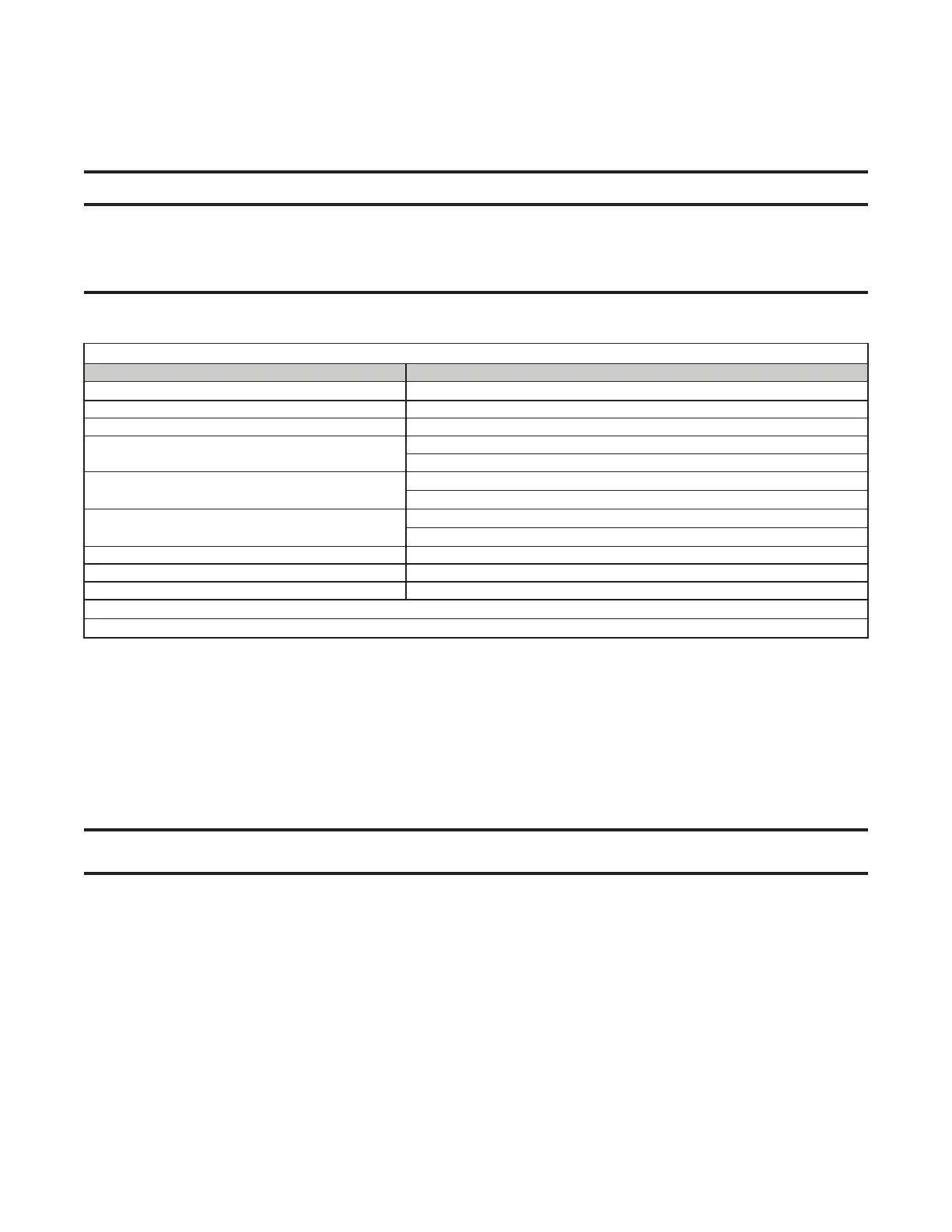
Table 18. Minimum Clearance Requirements for Horizontal Vent Termination Location
Component/Structure Minimum Clearance, All Directions Unless Specified (Feet (Meters))
Forced air inlet within 10 feet (3.1 meters)*
3 (0.9) above
Combustion air inlet of another appliance 6 (1.8)
Mechanical air supply inlet to any building Canada: 6 (1.8)
Any building opening (door, window, or gravity air inlet)
4 (1.2) horizontal and below
1 (0.3) above
Gas meter,** electric meter, and relief equipment
US: 4 (1.2) horizontal
Canada: 6 (1.8) horizontal
Gas regulator**
US: 3 (0.9) horizontal
Canada: 6 (1.8) horizontal
Adjoining building or parapet 6 (1.8)
Adjacent public walkway 7 (2.1) above
Grade (ground level) 3 (0.9) above
*Does not apply to the inlet of a direct vent appliance.
**Do not terminate the vent directly above a gas meter or service regulator.
28
UEZ-IOM (07-23) 1034347-I
INSTALLATION—CONTINUED
Vent Connections—Continued
Horizontal Vent Terminal (Option CC6) Installation—Continued
⚠ CAUTION ⚠
Products of combustion can cause discoloration of some building finishes and deterioration of
masonry materials. A clear silicone sealant normally used to protect concrete driveways may
be used to protect masonry materials from discoloration and deterioration. If discoloration is an
esthetic problem relocate the vent or install a vertical vent.
e. Refer to Table 18 to ensure that location complies with minimum clearance requirements.
2. Install vent pipe and combustion air pipe runs:
a. Connect piping to heater in accordance with specifications listed in Vent/Combustion Air System Piping
Requirements section.
b. Seal all joints in accordance with specifications listed in Vent/Combustion Air System Piping Joints section.
Due to high temperature considerations, do not enclose exhaust pipe or place pipe closer than 6 inches (152
mm) to combustible material.
c. Extend piping runs close to wall at location selected in step 1 and support piping in accordance with specifications
listed in Vent/Combustion Air System Piping Support section.
NOTE: The vent pipe will extend through the wall after the concentric adapter box is installed. The
indoor combustion air pipe will end at the concentric adapter box.
3. Cut hole through outside wall for combustion air pipe.
a. Ensure that outside wall construction thickness is between 1 inch (25 mm) minimum and 48 inches (1,219
mm) maximum.
b. Ensure that hole accommodates 8-inch (203-mm) combustion air pipe.
4. Connect concentric adapter box (see Figure 19):
a. Determine length of combustion air pipe by measuring wall thickness plus 4–16 inches (102–406 mm) beyond
minus width of pipe crimp that will be cut off.
b. Cut crimp off end of combustion air pipe so that 8-inch inlet air guard will fit properly.
c. Turn combustion air pipe so that is toward top side of concentric adapter box and slide it on collar.
d. Secure combustion air pipe to collar using sheet metal screws and seal joint and seam using sealant or tape.

 Loading...


