51
UEZ-IOM (07-23) 1034347-I
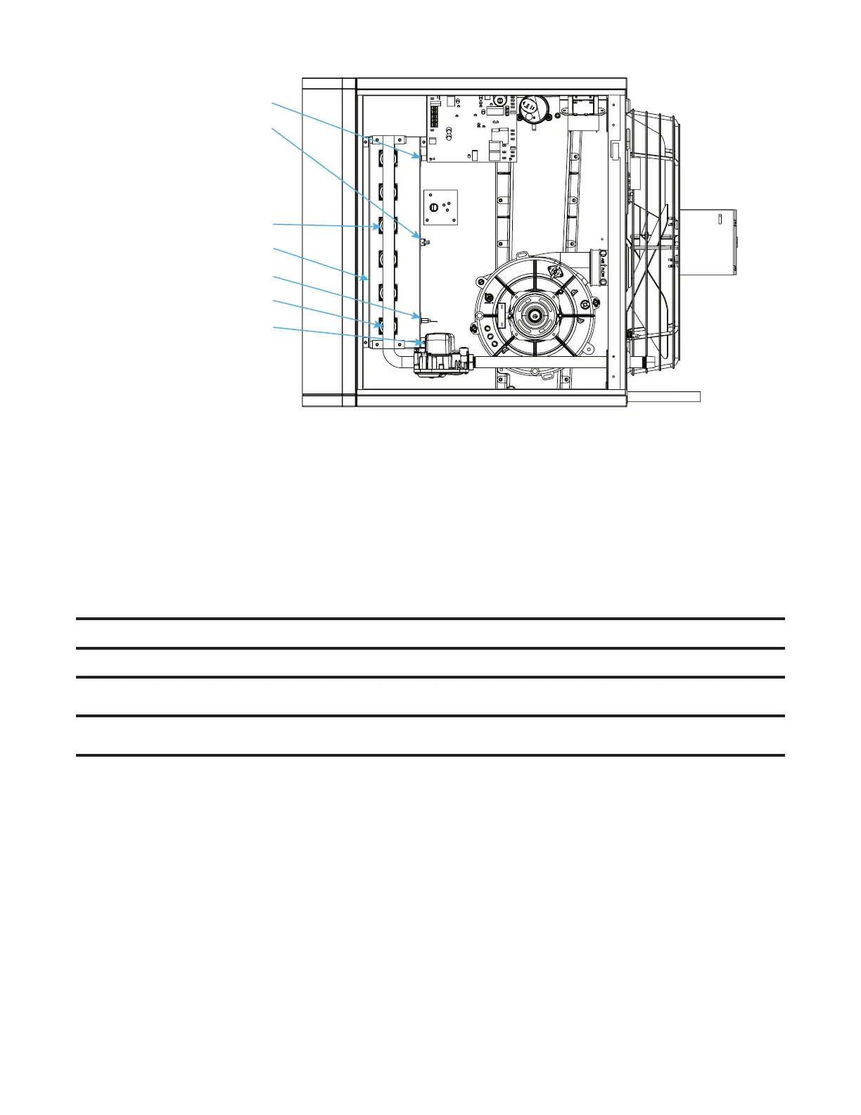
IGNITOR
GAS MANIFOLD
FLAME SENSOR
BURNER RACK
FLAME ROLLOUT SWITCH
INSHOT BURNER
Figure 31. Burner Compartment—Unit Sizes 055–110
1. Remove gas and electric supply:
a. Shut OFF gas supply ahead of union at manual valve outside cabinet.
b. Turn OFF electric supply.
c. Disconnect gas supply at union outside of cabinet.
2. Remove burner assembly (see Figure 31):
a. Remove access panel.
b. Disconnect gas train.
c. Mark and disconnect wires at combination gas valve, ignitor, flame sensor, and flame rollout switch.
⚠ CAUTION ⚠
Take care not to damage the ignitor while removing or cleaning the burner assembly.
3. Remove screws that secure gas manifold to burner box and carefully remove burner assembly.
NOTE: If, upon inspection, any burner components are damaged or deteriorated, replace the
burner assembly.
4. Shine flashlight on burners and use compressed air or vacuum cleaner to loosen and remove any accumulated
dust or debris.
5. Re-install burner assembly (see Figure 31):
a. Install burner assembly and gas manifold and secure gas manifold to burner box using screws removed in step 3.
b. Reconnect wires to combination gas valve, ignitor, flame sensor, and flame rollout switch.
c. Reconnect gas train.
d. Install access panel.
e. Reconnect gas supply at union outside of cabinet.
f. Leak test connection using leak detecting solution. If leak is detected, tighten connection. If leak cannot be
stopped by tightening connection, replace part(s).
6. Turn ON electric and gas.
7. Check for proper operation.

 Loading...


