51
UBXC-UDXC-IOM (01-24) 1042980-0
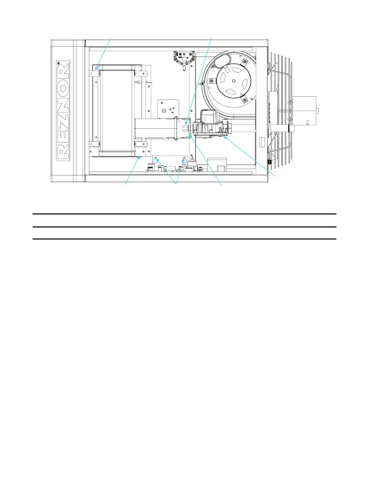
COMBINATION
GAS VALVE
VENTURI
TUBE
BURNER
ASSEMBLY
CONTROL ASSEMBLY
SECONDARY AIR BAFFLE(S)
ORIFICE ADAPTER
Figure 23. Burner Compartment (Typical)
⚠ CAUTION ⚠
Take care not to damage the ignitor while removing or cleaning the burner assembly.
2. Remove burner assembly (see Figure 23):
a. Remove access panel.
b. Disconnect gas train:
(1) Mark and disconnect wires at combination gas valve.
(2) Carefully remove burner orifice and orifice adapter locking nut.
(3) Slide orifice adapter out through bracket on venturi tube while pushing gas train to right. This will move
gas train out of way.
c. Detach control assembly:
(1) Remove two screws that secure control assembly bracket.
(2) Being careful not to disconnect any wires, slide control assembly to right.
d. Remove secondary air baffle(s) (unit sizes 60–400 only):
(1) Locate flat plate(s) identified as secondary air baffle(s)—vertical along right side of burner. Quantity of
baffles could be one to four depending on heater size. Each baffle is held in place by one screw.
(2) For correct re-assembly on secondary air shield, mark location (top and bottom) of each baffle.
(3) Remove screw(s) and remove baffle(s) (all).
e. Locate burner body supports—depending on size, burner will have two or more supports. At each support,
remove one screw that secures support to secondary air shield.
f. While holding venturi tube, slide entire burner assembly slightly to right to disengage burner from supports on left.
g. Rotate open end of venturi tube inward toward heater and carefully pull burner assembly out of cabinet.