23
IMPORTANT: The EcoNet™ control
system requires continuous 18 AWG thermostat
wire. DO NOT use phone cord to connect
indoor and outdoor units. This will damage the
controls.
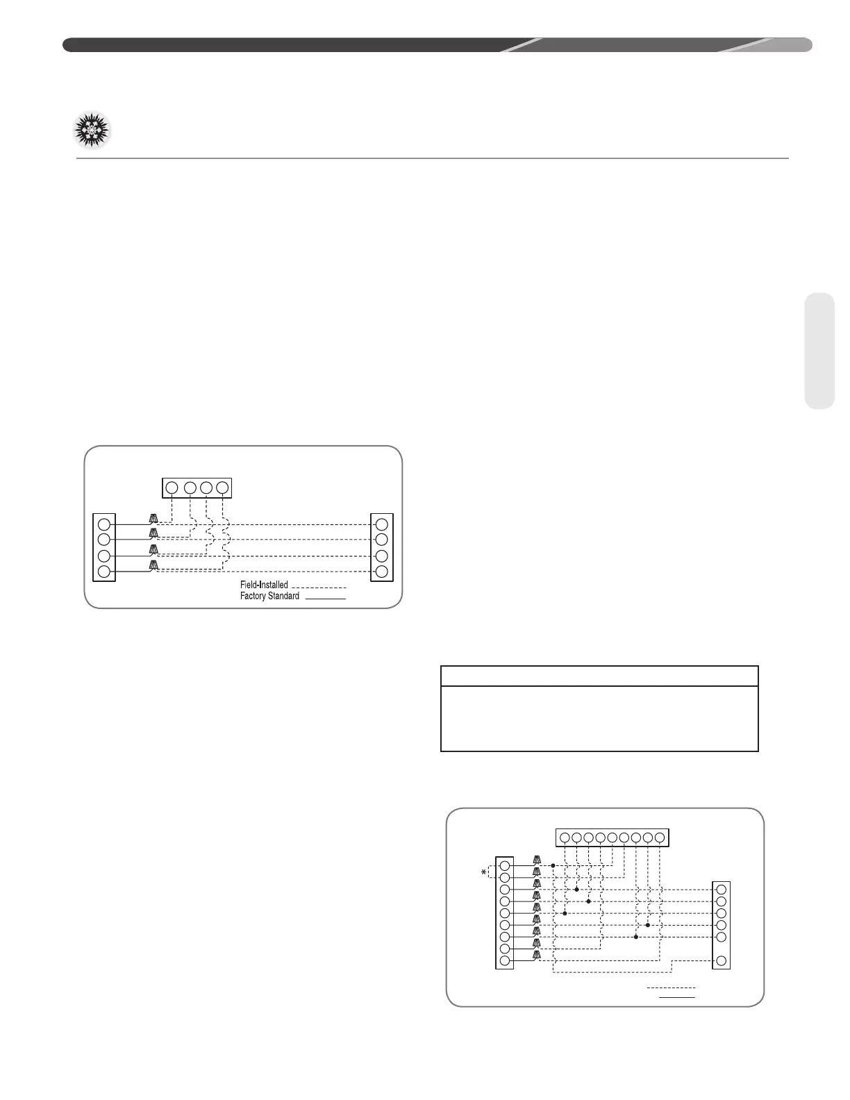
The EcoNet™ control system requires four (4)
control wires for unit operation:
• R 24 VAC
• C 24 VAC common
• Data wire E1 Communications
• Data wire E2 Communications
The EcoNet™ enabled air handler or furnace is
equipped with a 24-volt, 40 or 50 VA transformer
for proper system operation. See the wiring
diagram below for low voltage wiring connections.
These wires need to be connected to each device
(Control Center, indoor air handler or furnace, and
outdoor unit).
Once all devices are connected, apply the line
voltage to the indoor and outdoor units.
When all devices are powered, the EcoNet™
Control Center should detect the indoor and
outdoor units within 45 seconds.
Once the system is powered and all components
are communicating with each other, the airflow
settings will be automatically configured in the air-
handler or furnace.
All adjustments for indoor airflow are made at the
EcoNet™ Control Center from this point. Items
that can be changed are airflow trim adjustment,
on-demand dehumidification, cooling and heating
airflow and electric heat airflow. The Control
Center also has a wide range of fault and history
information. To access any of the control center
menus press the settings, status, or service icons
at the bottom of the touch screen. Refer to the
air handler or furnace installation manual and
the EcoNet™ Control Center installation manual
for further details on setting up the system and
available adjustment options.
4.9.4 Conventional 24 VAC
Thermostat Control Wiring
Connection
The (-)P17 series of heat pumps allow the installer
to use conventional 24 VAC control wiring and a
conventional thermostat for limited unit operation.
IMPORTANT: The preferred method
of unit installation and operation is by the EcoNet™
Communicating System, which allows access to
the fault history of the system. This diagnostic
information is not available at the thermostat when
the (-)P17 unit is using a conventional thermostat.
See “EcoNet™ Control Board Communicating
Wiring” in section 4.9.3.
Thermostat control wiring requires a minimum of
six (6) wires for proper unit operation:
R – 24 VAC
C – 24 VAC common
Y – First-stage operation
Y2 – Second-stage operation
B – Heat pump operation
W – Defrost
The following figures show the typical wiring
diagrams with (-)H2T/(-)HMV air handler and (-)P17
heat pump.
Wiring
4.0 INSTALLATION
Indoor
Unit
BR/W
PR
R
BR
E1
E2
C
R
EcoNet™
Control Center
Outdoor
Unit
E1
E2
C
R
E1
E2
C
R
4.9 Control Wiring (cont.)
TYPICAL 2-STAGE THERMOSTAT: (-)P17 HEAT PUMP
WITH ELECTRIC HEAT USING A TWO-STAGE
THERMOSTAT WITH DEHUMIDIFICATION
Field-Installed
Factory Standard
(-)H2T or (-)HMV
Air Handler
(-)P17
Heat Pump
Outdoor Unit
Typical Two-Stage Thermostat
W1
W2
Y1
Y2
B
R
C
G
ODD
B
Y1
Y2
G
E/W1
W2
C
R
DHM
Y
Y2
B
R
C
W
W/BK
W/BL
Y
Y/BL
BL
R
BR
G/BR
G/Y
WIRE COLOR CODE
BK – BLACK GY – GRAY W – WHITE
BR – BROWN O – ORANGE Y – YELLOW
BL – BLUE PR – PURPLE
G – GREEN R – RED
 Loading...