24
It is important that proper electrical power is
available at the heat pump power terminal block. The
acceptable operating voltage range is shown below.
VOLTAGE RANGES
Install a branch circuit disconnect within sight of the
unit and of adequate size to handle the minimum
circuit ampacity (MCA) current (see “Electrical Data”
in Section 3.2).
Field wiring must comply with the National Electric
Code (C.E.C. in Canada) and any applicable local code.
Power wiring must be run in a rain-tight conduit.
Conduit must be attached to the hole in the bottom
of the control box.
Connect power wiring to line-voltage lugs on the
terminal block located in the outdoor heat pump unit
electrical box. (See wiring diagram attached to unit
access panel.)
Check all electrical connections, including factory
wiring within the unit and make sure all connections
are tight.
DO NOT connect aluminum field wire to the line
voltage terminal block.
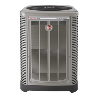
TYPICAL 2-STAGE THERMOSTAT: HEAT PUMP WITH
ELECTRIC HEAT
Field-Installed
Factory Standard
(-)H2T or (-)HMV
Air Handler
(-)P17
Heat Pump
Outdoor Unit
Typical Two-Stage Thermostat
W/BK
W/BL
Y
Y/BL
BL
R
BR
G/BK
W1
W2
Y1
Y2
B
R
C
G
ODD
B
Y1
Y2
G
E/W1
W2
C
R
Y
Y2
B
R
C
W
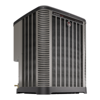
TYPICAL 2-STAGE THERMOSTAT: (-)P17 HEAT PUMP
WITH ELECTRIC HEAT USING A HUMIDISTAT FOR
HUMIDIFICATION
Field-Installed
Factory Standard
(-)H2T or
(-)HMV
Air Handler
(-)P17
Heat Pump
Outdoor Unit
Typical Two-Stage Thermostat
W1
W2
Y1
Y2
B
R
C
G
ODD
B
Y1
Y2
G
E/W1
W2
C
R
Y
Y2
B
R
C
W
Humidistat
W/BK
W/BL
Y
Y/BL
BL
R
BR
G/BK
G/Y
All wires are field installed.
*Add jumper between W1 and W2 for maximum
temperature rise if desired.
WIRING
Wiring
4.9 Control Wiring (cont.)
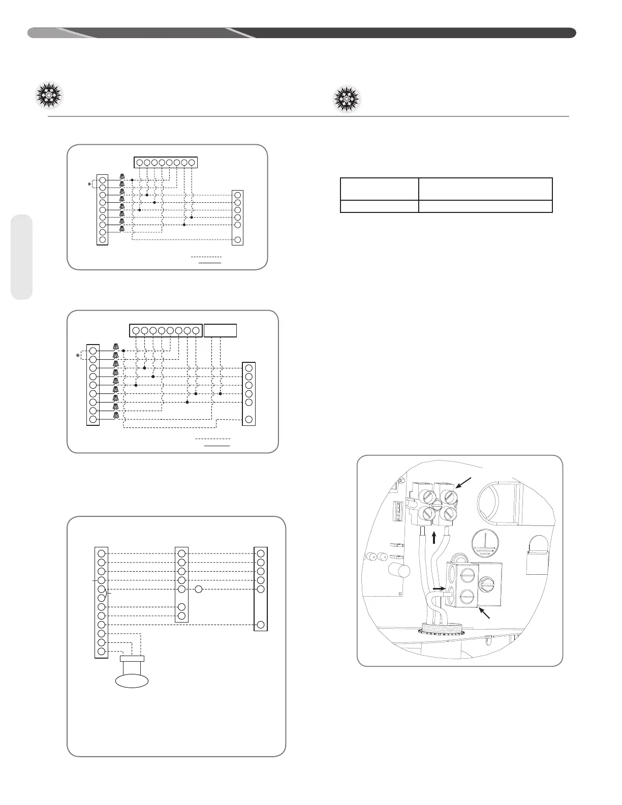
NOTES:
(1) FOR PROGRAMMING THERMOSTAT IN DUAL-FUEL APPLICATION, SEE
THERMOSTAT INSTALLATION INFORMATION.
(2) FOR REMOTE SENSOR INSTALLATION, SEE THERMOSTAT INSTALLATION INFORMATION.
(3) OPTIONAL PLENUM SENSOR.
(4) FOR TWO STAGES, CONNECT W2 ON THERMOSTAT TO W2 ON THE CONTROL BOARD.
(5) EMERGENCY HEAT (E) CONNECTION MAY NOT BE ALLOWED BY LOCAL CODES.
(6) 2-STAGE HEAT PUMP ONLY.
R
C
W1
W/E
Y
(5)
(6)
Y2
G
W2
B
+
S
–
R
C
W
Y
Y2
B
W2
R
C
W
Y1
Y2
G
PS
(3)
Outdoor
Sensor
(2)
12 FT.
(3.7 M )
(-)P17
Heat Pump
Outdoor Unit
Typical
Two-Stage
Thermostat
Furnace
Control
TYPICAL 2-STAGE THERMOSTAT AND DUAL-FUEL
APPLICATION
4.10 Power Wiring
Voltage
Operating Voltage Range at
Maximum Load Conditions
7OHZL
Line Voltage Terminal Block
Ground Lug
 Loading...