2903411
2
1. BURNER DESCRIPTION
Gas burner with two stage progressive or modulating operation.
1.1 BURNER EQUIPMENT
Gas valve fitting + screws . . . . . . . . . . . . . . . . . . . . N° 1
Insulating gasket . . . . . . . . . . . . . . . . . . . . . . . . . . . N° 1
4 pin plug, 7 pin plug. . . . . . . . . . . . . . . . . . . . . . . . N° 1
Screws and nuts for boiler fixing flange . . . . . . . . . . N° 4
Instruction . . . . . . . . . . . . . . . . . . . . . . . . . . . . . . . . N° 1
Spare parts catalogue . . . . . . . . . . . . . . . . . . . . . . . N° 1
1.2 ACCESSORIES (optional)
Kit 7 pin/plug socket with filter: code 20076305
The connection kit filtered with a 7 pin/plug socket is necessary to counter the radio disturbances coming from
the electrical power supply.
Important:
the installer is responsible for the addition of any safety device not foreseen in this manual.
The burner conforms with European Directives:
Electromagnetic Compatibility 2004/108/EC, Low Voltage 2006/95/EC.
Gas train conforms with Gas Directive 90/396/EEC.
The burner has been tested to conform with the Directives EN60335 / EN50165.
To comply with the above-mentioned requirements it is necessary for the burner to be protected by a hood or
by the heat generator door. Removal of this protection must only be possible with the aid of a tool.
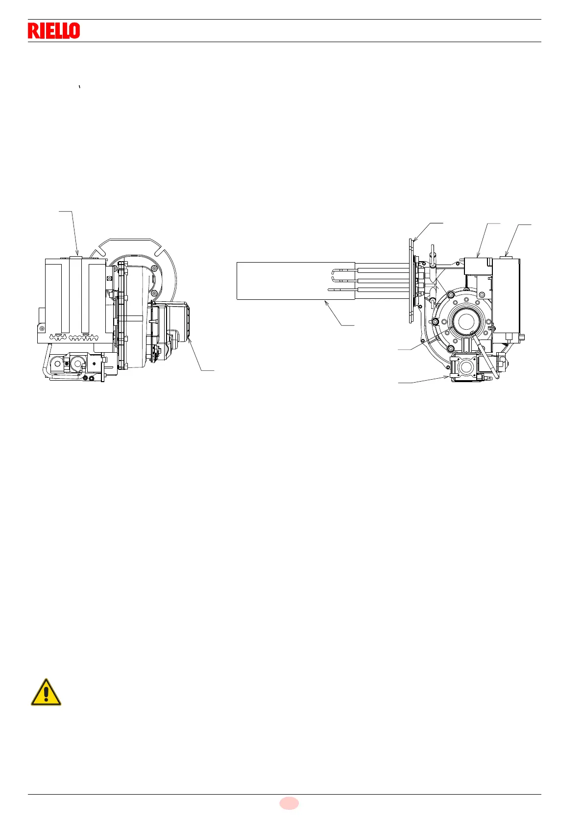
1 – Reset button with lockout warning
2 – Control box
3 –Gas valve
4 – Air/gas mixer in intake circuit
5 – Flange
6 – Motor
7 – Combustion head with metal mesh
8 – Ignition transformer
Fig. 1
D8609
 Loading...