2903411
4
3. INSTALLATION
THE BURNER MUST BE INSTALLED IN CONFORMITY WITH LEGISLATION AND LOCAL STANDARDS.
3.1 HEAT GENERATOR PLATE
Make holes in the plate shutting off the combustion chamber as
illustrated in fig. 2. The position of the threaded holes may be
marked using the gasket joint supplied with the burner.
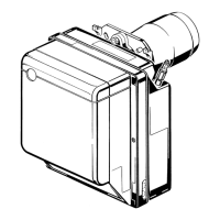
3.2 BOILER FIXING, (see fig. 3)
To install, proceed as follows:
Fasten the burner (1) to the boiler's door (2) by means of the
four screws and (where necessary) the nuts supplied, placing
the insulating gasket (3) between the two.
3.3 PROBE AND ELECTRODE POSITIONING
Before installing the burner on the boiler, make sure the probe and electrode are positioned cor-
rectly as in fig. 4.
Do not turn the electrode: position it as illustrated. Placing the electrode near the ionization probe
may result in the control box amplifier being damaged.
10
Probe
D8616
Electrode
Fig. 4
 Loading...