INSTALLATION
20
MODEL 50 - 70
AC-N OUT
CN9CN10
AC-L OUT
CN11
M
CN22
CN15
VALVE A
CN3
PE
BL(OR W)
Y/G
CN36
COMB
COMA
N
R
CN1
CN2
AC-N
AC-L
FUSE1
T25A 250VAC
CN24
CN23
MODULE COM
MODULE POWER
CN3
CN10
B
BL
BL
OR
CN5
CN1
CN4
CN8 CN9
CN2
CN11
CN6 CN7
B
M
R(U)
S(V)
C(W)
B
W
R
OUTDOOR PCB
MOUDLE PCB
Y/G
Y/G
1
2
3(C)
BL(OR W)
BL
U
V
W
P N
AC-L
LI
AC-N L0
CN25
N
P
CN28
21
GR GR
BR(OR B)
CAP
M
CAP
CN7
CN6
AC-N OUT
AC-L OUT
BR(OR B)
BL(OR W)
BL(OR W)
BR(OR B)
XQ
CN47
Compressor
Reactor
Power supply 230V-1F-50HzTo in door unit
4-WAY VALVE
DC FAN
ELECTRIC
EXPANSION VALVE
SUCTIO N
TEMP.SENSOR
Compressor sensor
Defrosting sensor
Outdoor air sensor
TC
CS
HW
2.12
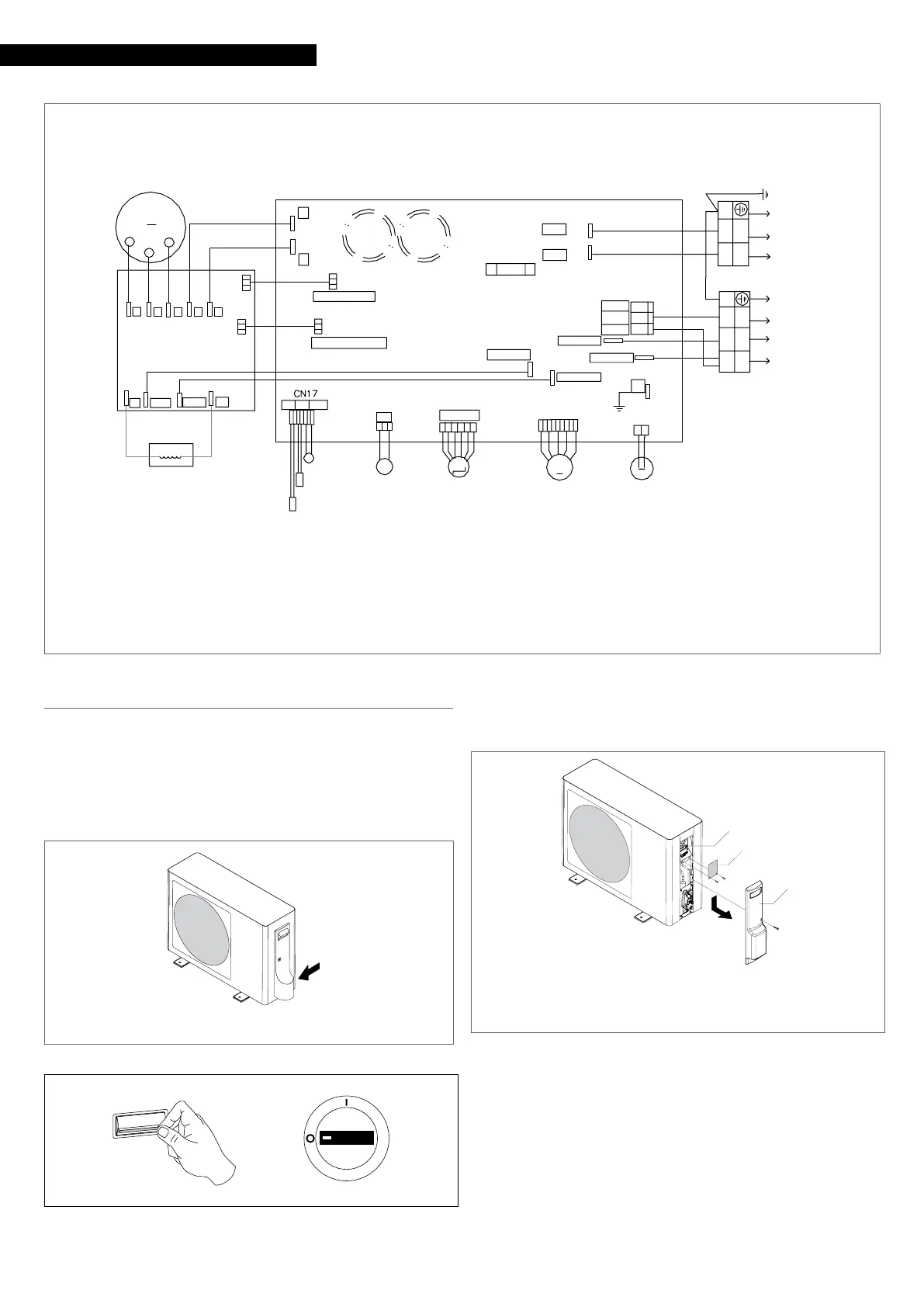
Electrical connection
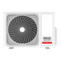
AARIA START It leaves the factory completely wired, and only re-
quires a connection to the electrical power grid, the installation
of a padlockable disconnecting switch, and a connection to the
indoor unit.
9
The unit must be powered with a separate electric circuit.
1 Electric connection input
1
ON
OFF
— set the system main switch to “OFF”
9
Wait 10 minutes before touching the device electric compo-
nents.
To access the terminal board:
1 Terminal blocks
2 Terminal board cover panel (model 50 - 70 only)
3 Connections cover
3
2
1
— unscrew the fastening screw
— push down the connection covering panel
— remove the connection covering panel
— unscrew the fastening screws
— remove the terminal board cover panel