INSTALLATION
21
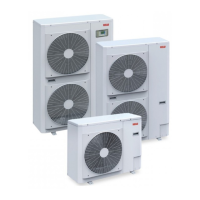
MODEL 25 - 35
1 Terminal blocks
2 Wire retainer
3 Earth screw
1
2
3
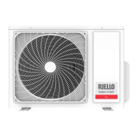
MODEL 50 - 70
1 Connection terminal board with indoor unit
2 Power supply connection terminal board
3 Wire retainer
4 Earth screw
1
3
2
4
— remove the wire retainer
— make electrical connections according to the diagrams be-
low
MODEL 25 - 35
A Outdoor unit
B Indoor unit
C System main switch
3(C)
1(N) 2(L)
1(N)2(L)
3(C)
B
A
N
L
230V 1-N 50HZ
C
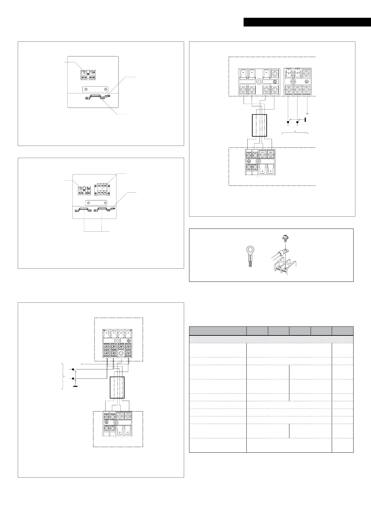
MODEL 50 - 70
A Outdoor unit
B Indoor unit
C System main switch
1(N)2(L)
3(C)
A
B
LN
230V 1-N 50HZ
C
1 (N) 2 (L)
3 (C)
1 (N) 2 (L)
9
It is compulsory to use ring crimp terminals to connect to the
terminal board.
For the sizing of the electrical power cables and safety devices,
use the following table:
Model 25 35 50 70
Electrical characteristics
Power supply 230/1/50
V/Ph/
Hz
Protection factor 24 IP
Protection against
short circuit
20 25 A
Protection against
overcurrent
15 20 A
Ground protection 20 25 A
Residual current 30 mA
Starting current 1,00 A
Power cable H07RN-F Type
Power cable 3 x 1,5 3 x 2.5
n. x
mm²
Signal cable 1 x 1
n. x
mm²
9
The cable sections specified in the table are minimum re-
quirements. The correct size must be calculated taking in-
to account the actual length, the type of routing and other
conditions set by the existing regulations.
— fasten the wires with the wire retainer
— complete the electric connections and refit all components