INSTALLATION
22
by performing the described operations in reverse order
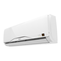
MODEL 25 - 35
1 Connections cover
1
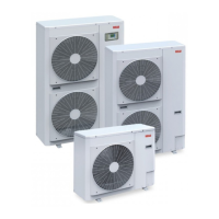
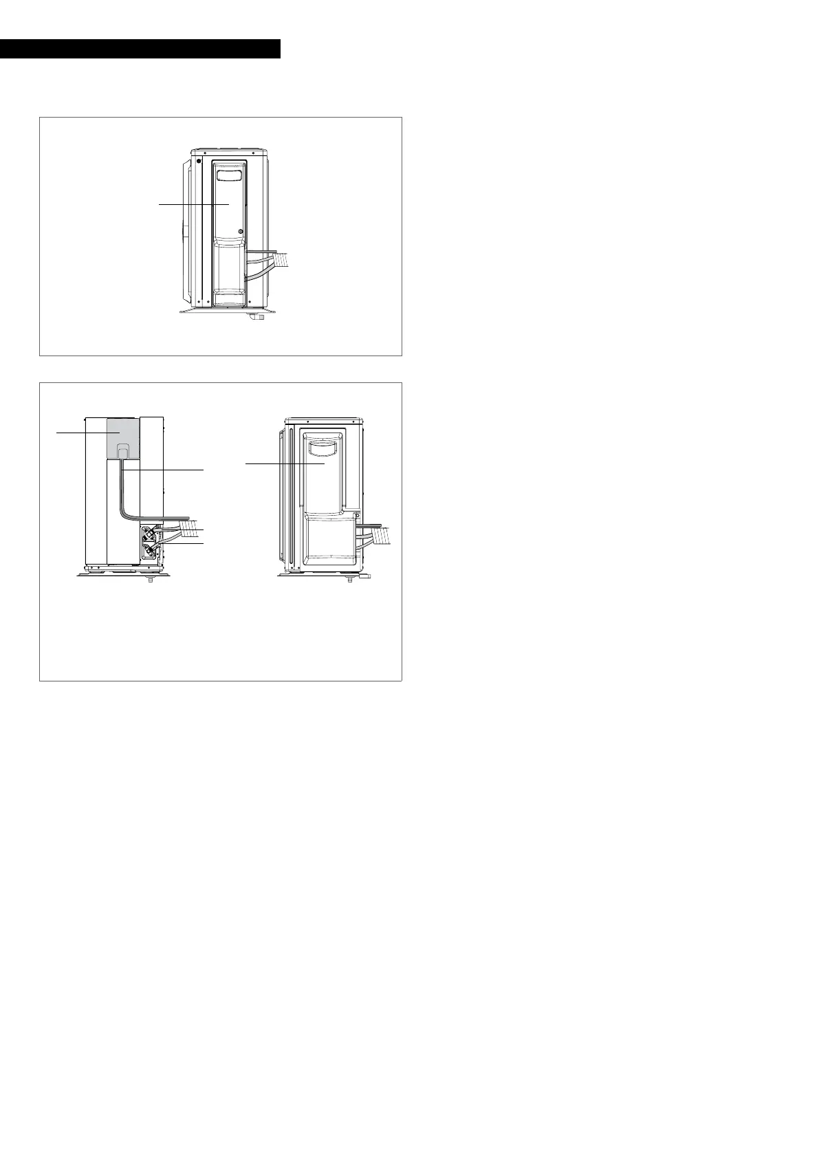
MODEL 50 - 70
1 Terminal board cover panel
2 Connection power cables
3 Gas pipe
4 Liquid pipe
5 Connections cover
1
2
3
4
5
Check that:
— the characteristics of the power network are suitable for
the device usage values
— the power supply voltage corresponds to the nominal val-
ue +/- 10%, with a maximum phase imbalance of 3%
— all of the power network disconnect devices must be
equipped with contact openings (3 mm) in order to allow
for complete disconnection, in accordance with the con-
ditions required
Mandatory items:
— have an omnipolar magneto-thermal circuit breaker and
a padlockable disconnecting switch compliant with the
IEC-EN Standards (contact opening of at least 3 mm), with
adequate breaking power and differential protection, in-
stalled near the equipment
— connect the device to a properly functioning earthing sys-
tem
— make sure that the electrical power supply system is com-
pliant with the current national safety standards
— make sure that the power supply line impedance is con-
sistent with the unit's power consumption, as indicated on
the unit's data plate
— for any electrical intervention, always refer to the wiring
diagrams contained within this booklet
— take anti-static precautions in case of weather conditions
where humidity is less than 40%
9
Electric connections shall be made in compliance with na-
tional regulations.
9
Avoid placing the connection cables less than 3 metres away
from radio and video systems.
9
Avoid using mobile phones.
0
It is forbidden to earth the device together with pipes,
lightning conductors or the earthing system of a telephone
line. Using an improper earthing system can cause electric
shocks.
0
It is forbidden to connect other devices in parallel to the
unit.